Flow regulation and control valve
A valve and flow technology, used in the field of flow control valves, can solve the problems of shortened valve life and valve body damage.
- Summary
- Abstract
- Description
- Claims
- Application Information
AI Technical Summary
Problems solved by technology
Method used
Image
Examples
Embodiment 1
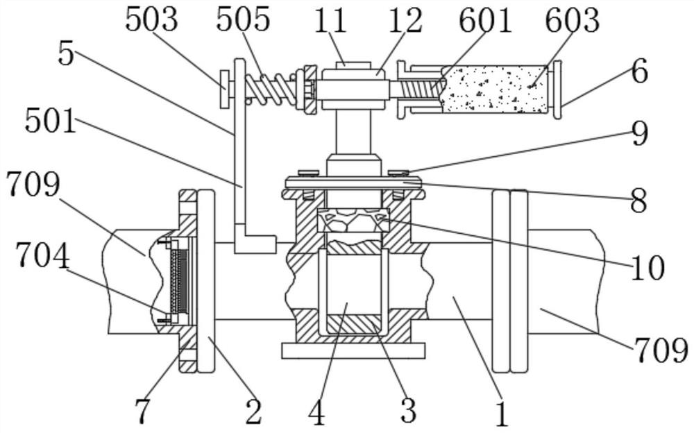
[0032] see figure 1 , 2 and 5, a flow control valve, comprising a valve body 1, a flange 2, a cylinder 3 and a through hole 4, the left and right sides of the valve body 1 are fixedly connected with the flange 2, and the inside of the valve body 1 is sleeved with a cylinder body 3, the outer wall of the cylinder 3 is in clearance fit with the valve body 1, the inside of the cylinder 3 is provided with a through hole 4, and the outer wall of the flange 2 is equipped with a filter mechanism 7;
[0033] The filter mechanism 7 includes two water pipes 709 fixedly connected with the two flanges 2, the inner wall of the water inlet of the water pipes 709 is provided with a fixing seat 704, and the inside of the fixing seat 704 is provided with a pillar 707 that runs through the fixing seat 704, and the pillar 707 is adjacent to the flange 2 is provided with a filter screen 703, and the end of the pillar 707 away from the flange 2 is provided with a limit block 706, and the end of t...
Embodiment 2
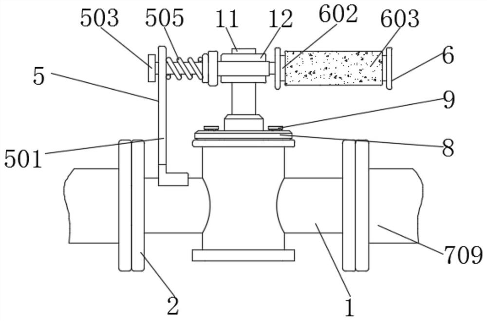
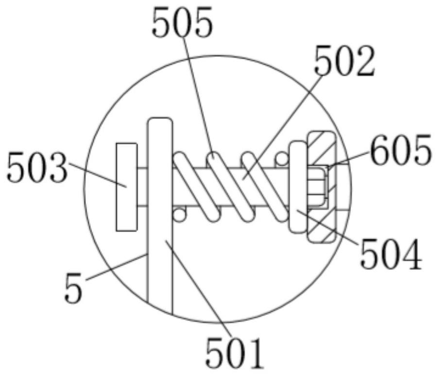
[0035] As an option, see Figure 1-3 , a flow control valve, the upper surface of the valve body 1 is fixed with a fixing mechanism 5, the fixing mechanism 5 includes a support plate 501, a cross bar 502, a baffle 503, a plug 504 and a first spring 505, the bottom end of the support plate 501 It is fixedly connected with the upper surface of the valve body 1, and the top of the support plate 501 is sleeved with a cross bar 502. Move in middle, the left end of cross bar 502 is provided with baffle plate 503, and the right end of baffle plate 503 is fixedly connected with cross bar 502, and the right end of cross bar 502 is provided with plug 504, and the right end of plug 504 is processed by bump, and the left end of plug 504 and The cross bar 502 is fixedly connected, and the outer wall of the cross bar 502 is sleeved with a first spring 505. The first spring 505 is in clearance fit with the cross bar 502. The left side of the first spring 505 is in contact with the outer wall...
Embodiment 3
[0037] As an option, see figure 1 , 2, 4 and 6, a flow control valve, the top outer wall of the cylinder 3 is sleeved with a partition 8, the inner wall of the partition 8 is matched with the outer wall of the cylinder 3, and the left and right sides of the partition 8 are screwed with bolts 9. The bolt 9 runs through the partition 8 and is threaded to the valve body 1. The left and right sides of the partition 8 are threaded to the valve body 1 through the bolt 9. The bolt 9 connects the partition 8 to the valve body 1. The cylinder 3 The outer wall is socketed with a rubber pad 10, the inner wall of the rubber pad 10 is in interference fit with the cylinder 3, the outer wall of the rubber pad 10 fits with the inner groove of the valve body 1, the cylinder 3 drives the rubber pad 10 to rotate, and the rubber pad 10 To play a sealing role, a vertical rod 11 is fixedly connected to the middle of the upper surface of the cylinder 1 , and a ferrule 12 is sleeved on the top of th...
PUM
 Abstract
Description
Claims
Application Information
 - R&D Engineer
- R&D Manager
- IP Professional
- Industry Leading Data Capabilities
- Powerful AI technology
- Patent DNA Extraction
Browse by: Latest US Patents, China's latest patents, Technical Efficacy Thesaurus, Application Domain, Technology Topic, Popular Technical Reports.
© 2024 PatSnap. All rights reserved.Legal|Privacy policy|Modern Slavery Act Transparency Statement|Sitemap|About US| Contact US: help@patsnap.com


