


Quick Research
Generate reliable direction feasibility study reports for your R&D in just a few steps.

Technical Q&A
Discover and master advanced knowledge NOW. Basics, ideas, possibilities, all at once.

Find Solutions
As an expert in R&D theories, this can generate solutions to your technical problems instantly.

Evaluate Feasibility
Analyze your overall solution with one click, know your potential R&D risks in advance.

Monitor Landscape
Get weekly tech updates, stay abreast of the latest tech innovations and key insights.
Region of interest positioning for longitudinal monitoring in quantitative ultrasound
A region of interest, ultrasound technology, applied in the direction of sound wave reradiation, ultrasound/sonic wave/infrasonic wave diagnosis, application, etc., can solve the problems of subjective and inaccurate ROI matching, unreliable diagnosis or prognosis, etc.
- Summary
- Abstract
- Description
- Claims
- Application Information
AI Technical Summary
Problems solved by technology
Method used
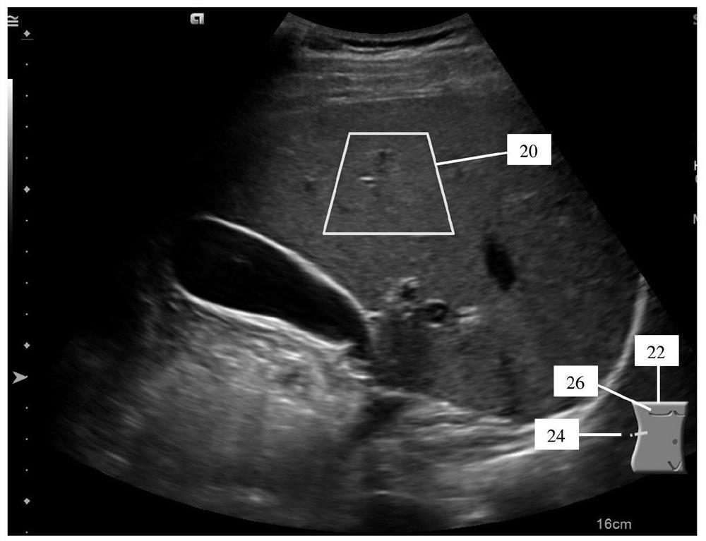
Image


Examples
Embodiment Construction
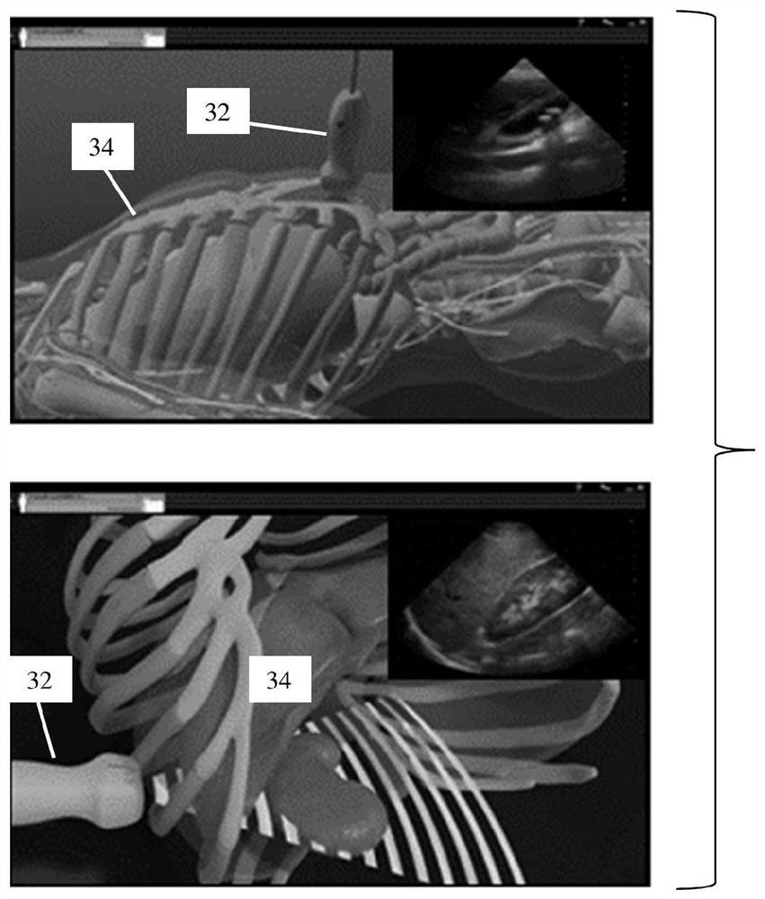
[0015] Provides automatic ROI placement in shear wave or other quantitative imaging. Indicators for ROI placement from previous exams are used to help place ROIs in the current exam, thereby providing QUS measurements of the same anatomy in different exams. This indicator is added to the image or different from the ROI shown on the image. This indicator helps locate FOV and ROI. Provides ROI localization for longitudinal monitoring using QUS. In order for ultrasound to be useful for monitoring, the process for finding and measuring the same anatomical region is automated.
[0016] In one embodiment, an indicator based on a measure of similarity between the current view and the reference view is used for ROI positioning. Indicator and correlation techniques are used to automate the process of finding the same anatomical location.
[0017] figure 1 One embodiment of a method for ROI localization in quantitative ultrasound imaging using an ultrasound scanner is shown. For l...
PUM
 Abstract
Description
Claims
Application Information
 - R&D Engineer
- R&D Manager
- IP Professional
- Industry Leading Data Capabilities
- Powerful AI technology
- Patent DNA Extraction
Browse by: Latest US Patents, China's latest patents, Technical Efficacy Thesaurus, Application Domain, Technology Topic, Popular Technical Reports.
© 2024 PatSnap. All rights reserved.Legal|Privacy policy|Modern Slavery Act Transparency Statement|Sitemap|About US| Contact US: help@patsnap.com