Auxiliary jig for PCB thin plate production

A production aid and fixture technology, used in electronic circuit testing, measuring devices, instruments, etc., can solve the problems of slow fixing, time-consuming, skewed, etc., to save clamping time, avoid detection on both sides, and improve detection. The effect of efficiency

Pending Publication Date: 2020-12-25
AOSHIKANG TECH CO LTD
View PDF0 Cites 1 Cited by
  • Summary
  • Abstract
  • Description
  • Claims
  • Application Information

AI Technical Summary

Problems solved by technology

[0003] In the PCB board production process, multiple PCB boards are required for inspection, and the general inspection organization needs to place the inspected PCB board on the template, and then use screws to fix the PCB board through the mounting holes on the PBC. to the template, but this fixing method is too slow, and the screw fixing generally does not achieve a good limit effect, and it is prone to deflection, resulting in inaccurate test structures, and the PCB needs to be tested on both sides, and generally All are turned manually, which is time-consuming and affects the efficiency of testing the PCB board

Method used


Image

  • Auxiliary jig for PCB thin plate production
  • Auxiliary jig for PCB thin plate production
  • Auxiliary jig for PCB thin plate production

Examples


no. 1 example

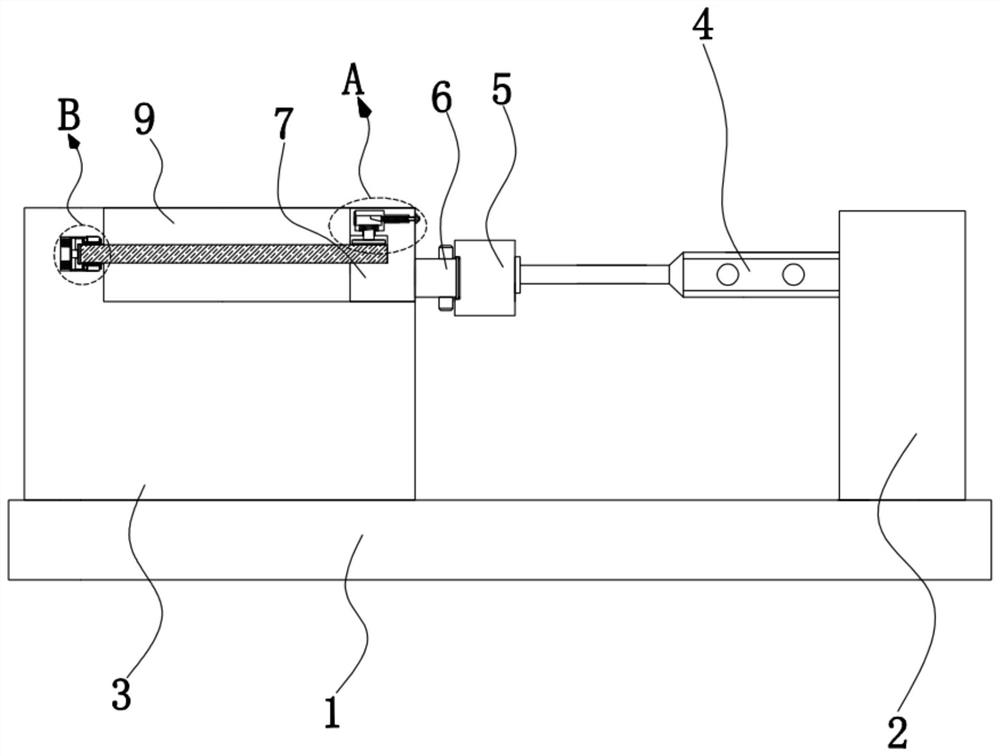
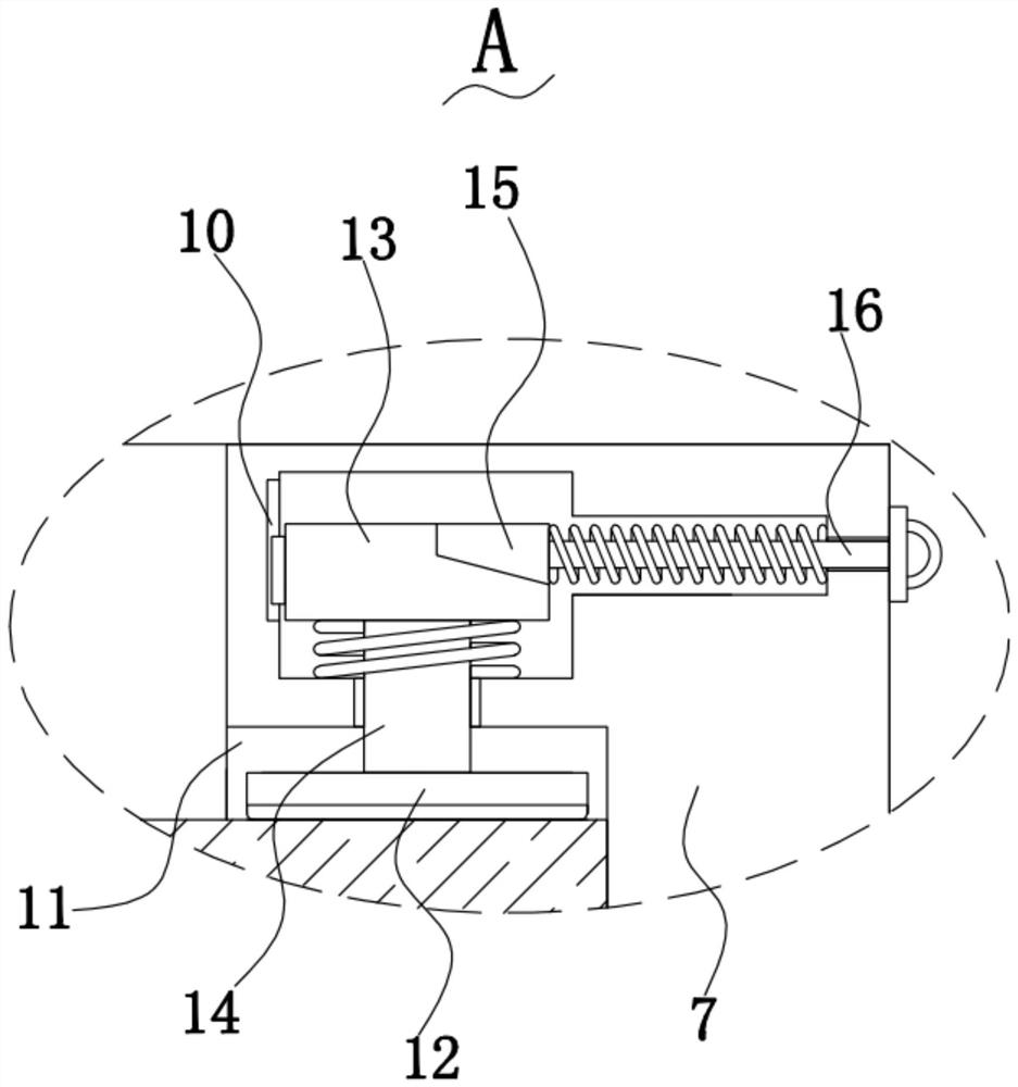
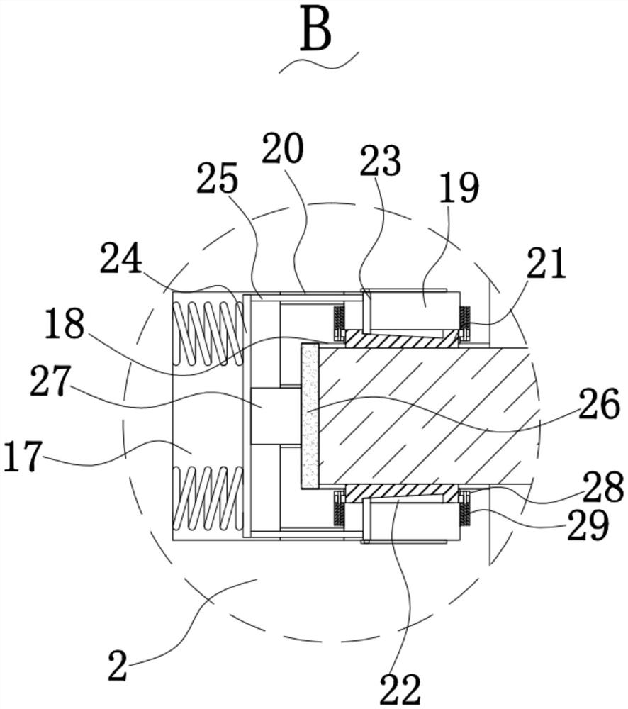
[0026] Please refer to Figure 1-Figure 4 , in the first embodiment of the present invention, the auxiliary jig for PCB sheet production includes: a base 1; a first fixed seat 2, the first fixed seat 2 is fixedly installed on the top of the base 1; a second fixed seat 3 , the second fixed base 3 is fixedly installed on the top of the base 1; hydraulic cylinder 4, the hydraulic cylinder 4 is fixedly installed on one side of the outer wall of the first fixed base 2; connecting block 5, the connecting block 5 The block 5 is fixedly mounted on the telescopic shaft of the hydraulic cylinder 4; the rotating rod 6 is mounted on the outer wall of one side of the connecting block 5; the clamping block 7 is fixed Installed on the end of the rotating rod 6 away from the connecting block 5; the motor 8, the motor 8 is fixedly installed on one side of the outer wall of the connecting block 5; the placing groove 9, the placing groove 9 is opened in the The top of the second fixed seat 3; t...

no. 2 example

[0038] Based on the auxiliary fixture for PCB sheet production provided in the first embodiment of the present application, the second embodiment of the present application proposes another auxiliary fixture for PCB sheet production. The second embodiment is only a preferred mode of the first embodiment, and the implementation of the second embodiment will not affect the independent implementation of the first embodiment.

[0039] The second embodiment of the present invention will be further described below in conjunction with the drawings and implementation methods.

[0040] Please refer to Figure 5 , PCB sheet production auxiliary jig also includes a fifth groove 30, the fifth groove 30 is opened on one side of the outer wall of the second fixing seat 3, fixed on one side of the outer wall of the second fixing seat 3 A connection frame 31 is installed, a cleaning fan 32 is fixedly installed on one side inner wall of the connection frame 31, a sixth groove 33 is provided o...


PUM


Abstract

The invention provides an auxiliary jig for PCB thin plate production. The auxiliary jig for PCB thin plate production comprises a base, a first fixing seat which is fixedly mounted at the top of thebase, a second fixing seat which is fixedly mounted at the top of the base, a hydraulic cylinder which is fixedly mounted on the outer wall of one side of the first fixing seat, a connecting block which is fixedly mounted on a telescopic shaft of the hydraulic cylinder, a rotating rod which is rotationally mounted on the outer wall of one side of the connecting block, a clamping block which is fixedly mounted at one end, far away from the connecting block, of the rotating rod, and a motor which is fixedly mounted on the outer wall of one side of the connecting block. The auxiliary jig for PCBthin plate production has the advantages of being convenient to use, high in clamping speed and capable of improving the detection efficiency.

Description

technical field [0001] The invention relates to the technical field of PCB auxiliary production, in particular to an auxiliary jig for PCB sheet production. Background technique [0002] PCB, the Chinese name is printed circuit board, also known as printed circuit board, is an important electronic component, a support for electronic components, and a carrier for electrical connections of electronic components. Since it is made by electronic printing, it is Known as a printed circuit board. [0003] In the PCB board production process, multiple PCB boards are required for inspection, and when the general inspection organization is inspecting, it is necessary to place the inspected PCB board on the template, and then use screws to fix the PCB board through the mounting holes on the PBC. to the template, but this fixing method is too slow, and the screw fixing generally does not achieve a good limit effect, and it is prone to deflection, resulting in inaccurate test structures...

Claims


Application Information

Patent Timeline
Patent Type & Authority Applications(China)
IPC IPC(8): G01R31/28G01R1/04
CPCG01R1/0425G01R31/2808
Inventor 李军
Owner AOSHIKANG TECH CO LTD
Why Eureka
Try Eureka