Water spraying dust settling device for civil construction site
A technology for construction sites and dust suppression devices, which is applied in construction, building structure, and building materials processing, etc., can solve the problems of limited water spraying range, affecting the dust suppression effect, and large volume, so as to improve the water spraying effect and avoid regional omissions. , the effect of improving the applicability
- Summary
- Abstract
- Description
- Claims
- Application Information
AI Technical Summary
Problems solved by technology
Method used
Image
Examples
Embodiment 1
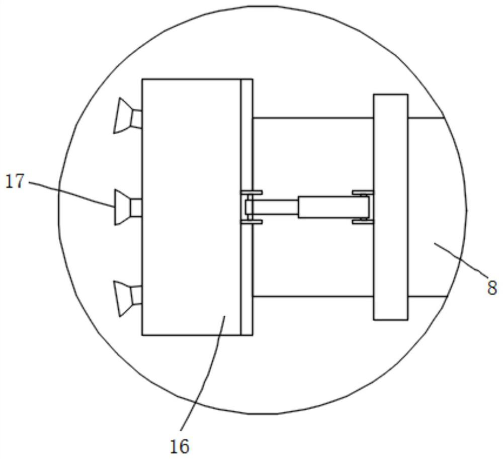
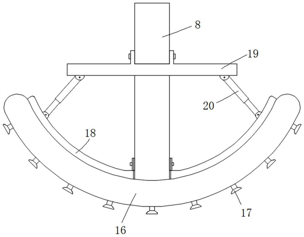
[0030] Embodiment 1, refer to figure 1 , figure 2 and image 3 : A sprinkler and dust suppression device for a civil construction site, comprising a base plate 1, a water tank 4 and a pump body 6 are fixedly installed on the top of the base plate 1, a water outlet pipe 5 is fixedly installed at the water outlet of the water tank 4, and one end of the water outlet pipe 5 away from the water tank 4 is connected to the The water inlet end of the pump body 6 is connected, the top of the bottom plate 1 is fixedly installed with a rotating member 12, the top of the rotating member 12 is installed with a fixed frame 11, and the fixed frame 11 is provided with a first movable groove 1101 and a second movable groove 1102. The two movable grooves 1102 are located above the first movable groove 1101 , two connecting rods 28 are rotatably arranged on the inner wall of the second movable groove 1102 , and the pipe body 8 is fixedly installed between the two connecting rods 28 , and the w...
Embodiment 2
[0031] Embodiment 2, refer to figure 1 and Figure 4: A reinforcing pad 9 is fixedly installed at the bottom of the pipe body 8, a partition plate 21 is fixedly installed in the first movable groove 1101, a first motor 22 is fixedly installed at the bottom of the inner wall of the first movable groove 1101, and the output end of the first motor 22 is fixed A screw rod 26 is installed, the smooth section of the screw rod 26 is located in the partition plate 21, the threaded section of the screw rod 26 is threadedly connected with a moving block 27, one side of the moving block 27 is rotated and provided with a straight rod 10, and the straight rod 10 is away from the moving block. The movement of 27 is rotatably connected with the reinforcing pad 9, the inner wall of the first movable groove 1101 is provided with a chute 24, a sliding block 25 is slidably arranged in the sliding groove 24, and a fixing rod 23 is fixedly installed on the outer wall of the sliding block 25, and i...
Embodiment 3
[0032] Embodiment 3, refer to figure 1 , image 3 and Figure 5 : The rotating member 12 includes a base 1201, an inner cavity is opened in the base 1201, a circular block 1202 is rotatably arranged in the inner cavity, a cylinder 1204 is fixedly installed on the top of the circular block 1202, and one end of the cylinder 1204 is rotated and arranged in the base 1201. When in use, the round block 1202 can rotate with the cylinder 1204 in the inner cavity, and a bearing can be installed in the inner cavity to reduce the friction when the round block 1202 rotates. A second motor 13 is fixedly installed on the top of the second motor 13, a shaft is fixedly installed at the output end of the second motor 13, and a second sheave 14 is fixedly installed on the top of the shaft. Connection, the bottom of the bottom plate 1 near the four corners are fixedly installed with a universal wheel 2, the top right edge of the bottom plate 1 is fixedly installed with a push rod 3, and the pu...
PUM
 Abstract
Description
Claims
Application Information
 - R&D
- Intellectual Property
- Life Sciences
- Materials
- Tech Scout
- Unparalleled Data Quality
- Higher Quality Content
- 60% Fewer Hallucinations
Browse by: Latest US Patents, China's latest patents, Technical Efficacy Thesaurus, Application Domain, Technology Topic, Popular Technical Reports.
© 2025 PatSnap. All rights reserved.Legal|Privacy policy|Modern Slavery Act Transparency Statement|Sitemap|About US| Contact US: help@patsnap.com


