Eureka AIR delivers breakthrough ideas for toughest innovation challenges, trusted by R&D personnel around the world.

Deburring turnover mechanism

A technology of turning mechanism and clamping mechanism, which is applied in metal processing and other directions, and can solve problems such as difficulty in meeting assembly line automation requirements and low efficiency

Pending Publication Date: 2020-12-25
SHENZHEN HUIKE PRECISION IND
View PDF0 Cites 0 Cited by
  • Summary
  • Abstract
  • Description
  • Claims
  • Application Information

AI Technical Summary

Problems solved by technology

After the burrs on one side are processed, the processed item needs to be turned over to the other side. The efficiency of manual turning is low and it is difficult to meet the automation requirements of the assembly line.

Method used


Image

  • Deburring turnover mechanism
  • Deburring turnover mechanism
  • Deburring turnover mechanism

Examples


Embodiment Construction

[0054] In order to enable those skilled in the art to better understand the solutions of the present invention, the technical solutions in the embodiments of the present invention will be clearly and completely described below in conjunction with the drawings in the embodiments of the present invention. Unless otherwise defined, all technical and scientific terms used herein have the same meaning as commonly understood by one of ordinary skill in the technical field of the invention. The terms used herein in the description of the present invention are for the purpose of describing specific embodiments only, and are not intended to limit the present invention.

[0055] Reference herein to an "embodiment" means that a particular feature, structure, or characteristic described in connection with the embodiment can be included in at least one embodiment of the present invention. The occurrences of this phrase in various places in the specification are not necessarily all referrin...


PUM


Abstract

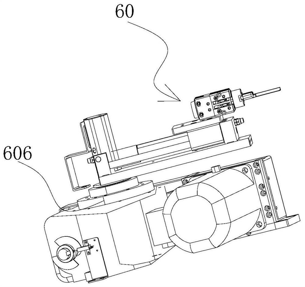
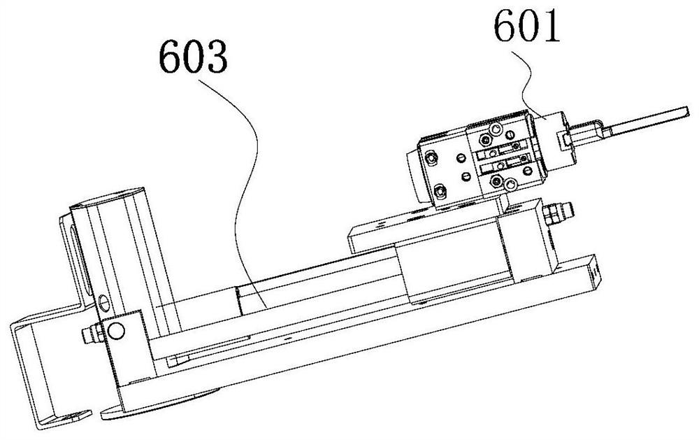
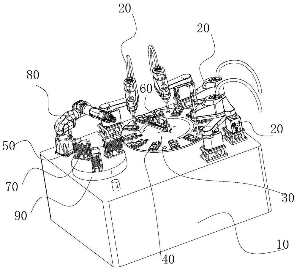
The invention discloses a deburring turnover mechanism. The deburring turnover mechanism comprises a clamping mechanism and a turnover mechanism; the clamping mechanism is used for clamping a machinedobject on a jig; and the turnover mechanism is connected with the clamping mechanism, and the turnover mechanism is mounted and arranged on a first rotating unit or a control table and used for driving the clamping mechanism to turn over and rotate so as to turn over the machined object on the jig through the clamping mechanism. In the deburring machining process of a product, after machining ofburrs on one face is completed, clamping arms can be opened through the clamping mechanism, the machined object is clamped, and the machined object is turned over to the other face under the action ofthe turnover mechanism, so that the two faces of an aluminum middle frame of a mobile phone are conveniently deburred, manual turnover is not needed, the automation degree is high, and the two facesof the machined object can be deburred.

Description

technical field [0001] The invention relates to the technical field of front removal processing, in particular to a turning mechanism for front removal. Background technique [0002] During the manufacturing process of mobile phone aluminum middle frame materials, edge burrs are likely to occur due to molds and other reasons, which will affect product realization, and the de-approval is mainly manual work. There is an urgent need; however, there is currently no reliable, automated way to automate the job. There are great limitations in the manual operation method, which seriously hinders the realization of full-line automation. At present, there is no effective automatic device that can automate the batching process; relying solely on manual work is not conducive to the production of large-scale full-process automatic mechanical devices. [0003] When de-cutting the processed article, it is usually necessary to perform de-cutting on both sides of the processed article. Af...

Claims


Application Information

Patent Timeline
IPC IPC(8): B23Q7/04
CPCB23Q7/048
Inventor 章继波
Owner SHENZHEN HUIKE PRECISION IND
Why Eureka
Eureka Blog
Learn More