Flue gas waste heat storage device

A heat storage device, flue gas waste heat technology, applied in heat storage equipment, heat exchanger types, indirect heat exchangers, etc. Equipment operating efficiency, improving energy utilization, and small size

Pending Publication Date: 2020-12-22
SHANGHAI ELECTRICGROUP CORP
View PDF0 Cites 0 Cited by
  • Summary
  • Abstract
  • Description
  • Claims
  • Application Information

AI Technical Summary

Problems solved by technology

[0005] (1) The recovery efficiency of the existing flue gas waste heat recovery device is not high, resulting in a serious waste of heat source, and at the same time, the environmental protection benefit is poor, so it is not suitable for popularization and application, mainly because the speed of flue gas is very fast, and the heat conduction efficiency of the traditional water heat exchange method is low , resulting in a large amount of heat loss;
[0006] (2) Recovering the waste heat in the flue gas with water will make the equipment bulky and occupy a large area

Method used


Image

  • Flue gas waste heat storage device
  • Flue gas waste heat storage device
  • Flue gas waste heat storage device

Examples


Embodiment 1

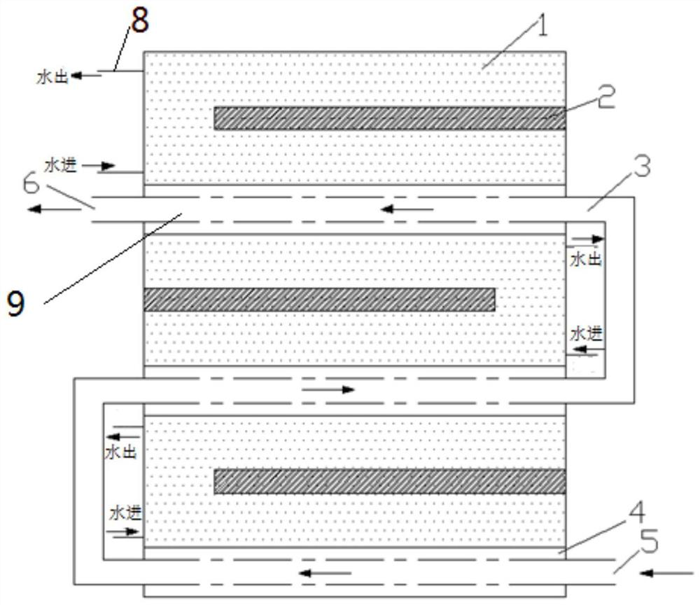
[0052] Such as figure 1 As shown, a preferred embodiment of the present invention provides a flue gas waste heat heat storage device, including:

[0053] A plurality of heat storage units, specifically, three heat storage units in this embodiment.

[0054] Wherein, each heat storage unit includes a molten salt heat storage body 1 , a solid heat storage body 4 and a heater 2 . The molten salt heat storage body 1 is composed of a molten salt heat storage material and a molten salt storage tank, and the solid heat storage body 4 is composed of a plurality of solid heat storage bricks 7, forming a hollow flue gas channel 9, and the three heat storage units Combined together to form a whole, the heater 2 is arranged inside the molten salt heat storage body 1 and evenly arranged around it. The solid heat storage body 4 is arranged below the molten salt heat storage body 1 .

[0055] Through such a structure, the traditional large-volume molten salt heat storage body is changed in...

Embodiment 2

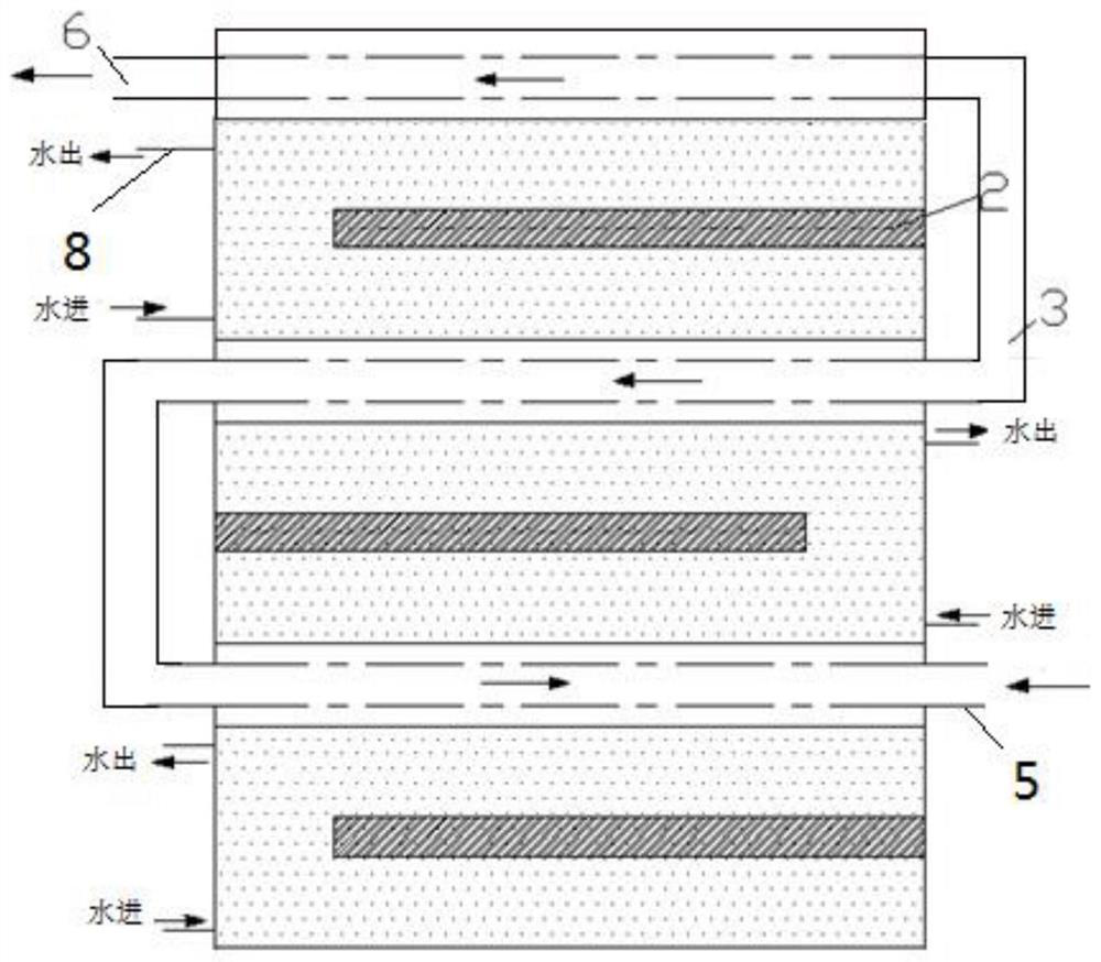
[0072] Such as image 3 As shown, another preferred embodiment of the present invention provides a flue gas waste heat heat storage device. The difference with the above-mentioned embodiment is that:

[0073] Each heat storage unit includes a molten salt heat storage body 1 , a solid heat storage body 4 and a heater 2 , and the solid heat storage body 4 is arranged above the molten salt heat storage body 1 . An electric heater 2 is arranged inside the molten salt heat storage body 1 for supplementing energy, and the heaters 2 are arranged around the molten salt heat storage body 1 .

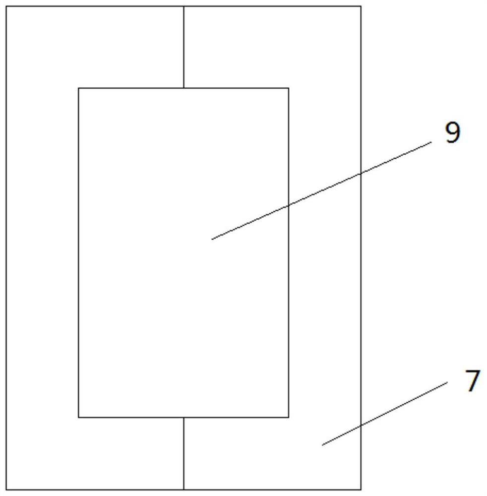
[0074] In this embodiment, specifically, the heat storage bricks are solid magnesia bricks. Each solid magnesia brick is closely arranged and combined to form a flue gas channel 9 .

Embodiment 3

[0076] Such as Figure 4 As shown, the difference between this embodiment and the above-mentioned two embodiments is that there are multiple flue gas passages 9 composed of solid heat storage bricks 7 in each heat storage unit, and the multiple passages are connected in parallel to enter and exit the heat storage The flue gas pipeline 3 of unit is all one. The flue gas passages 9 passing through the solid heat storage body 4 are all arranged in the heat storage unit. The path of high-temperature flue gas flowing in the flue gas channel 9 is shown in Figure 4 indicated by the middle arrow.


PUM


Abstract

The invention discloses a flue gas waste heat storage device. The device comprises a plurality of heat storage units, wherein each heat storage unit comprises a fused salt heat storage body, a solid heat storage body and a heater; the solid heat storage bodies form hollow flue gas channels; some flue gas channels are arranged in the fused salt heat storage bodies; the plurality of heat storage units are combined together to form a whole; and the heaters are arranged in the fused salt heat storage bodies. The flue gas waste heat storage device provided by the invention is high in heat utilization rate and high in heat conduction efficiency; and the problems that a flue gas waste heat recovery device is large, complex in structure and inflexible in use are solved.

Description

technical field [0001] The invention belongs to the field of heat storage, in particular to a smoke waste heat heat storage device. Background technique [0002] Energy consumption in my country's industrial sector accounts for about 70% of the country's total energy consumption, and the average unit energy consumption of major industrial products is about 30% higher than the international advanced level. In addition to factors such as relatively backward production technology and unreasonable industrial structure, the low utilization rate of industrial waste heat is an important reason for high energy consumption. my country's energy utilization rate is only about 33%, which is about 10% lower than that of developed countries, and at least 50%. Industrial energy consumption is directly discarded as waste heat in various forms. Therefore, our country is rich in industrial waste heat resources, which widely exist in the production process of various industries. Waste heat res...

Claims


Application Information

Patent Timeline
Patent Type & Authority Applications(China)
IPC IPC(8): F28D20/00
CPCF28D20/0034Y02E60/14
Inventor 仇秋玲顾清之张艳梅顾晓鸥张素娟赵伟杰
Owner SHANGHAI ELECTRICGROUP CORP
Why Eureka
Try Eureka