
Rail clamping device, rail and mounting method of rail clamping device

A technology for rail clamps and mounting parts, which is applied in the direction of supporting machines, mechanical equipment, machine tables/brackets, etc., which can solve the problems of complex structure and high cost of rail clamps, and achieve anti-loosening effect, low installation cost and maintenance cost , Versatile effect

Active Publication Date: 2020-12-22
CRRC QINGDAO SIFANG ROLLING STOCK RES INST
View PDF6 Cites 0 Cited by
  • Summary
  • Abstract
  • Description
  • Claims
  • Application Information

AI Technical Summary

Problems solved by technology

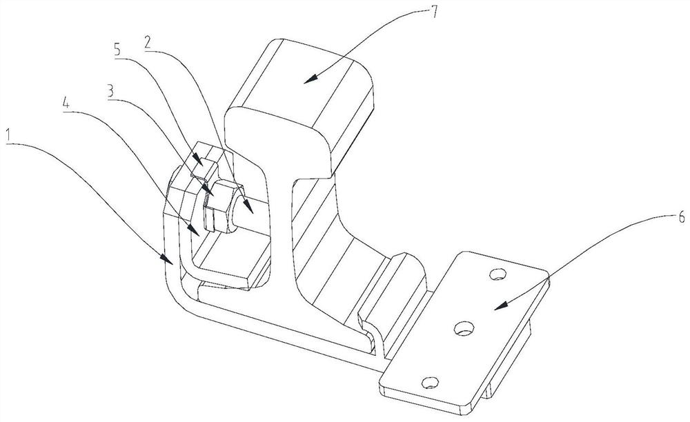
[0005] In order to solve the technical problem of complex structure and high cost of the rail clamp in the prior art, the present invention provides a rail clamp with a simple structure, which realizes the fixing of the rail clamp and the rail, thereby realizing mutual induction coils, sensors, etc. Equipment installation, installation cost and maintenance cost are low, suitable for occasions with a large number of applications

Method used


Image

  • Rail clamping device, rail and mounting method of rail clamping device
  • Rail clamping device, rail and mounting method of rail clamping device
  • Rail clamping device, rail and mounting method of rail clamping device

Examples


Embodiment Construction

[0046] In order to enable those skilled in the art to better understand the technical solutions of the present invention, the present invention will be further described in detail below in conjunction with the accompanying drawings and specific embodiments. While embodiments of the invention are disclosed in the drawings, it should be understood that the invention may be embodied in any form and should not be limited by the illustrated embodiments.

[0047] In the description of the present invention, it should be understood that the orientations or positional relationships indicated by the terms "inner", "outer", "upper", "lower", "left", "right" etc. are based on those shown in the accompanying drawings. Orientation or positional relationship is only for the convenience of describing the present invention and simplifying the description, and does not indicate or imply that the referred device or element must have a specific orientation, be constructed and operated in a specif...


PUM


Abstract

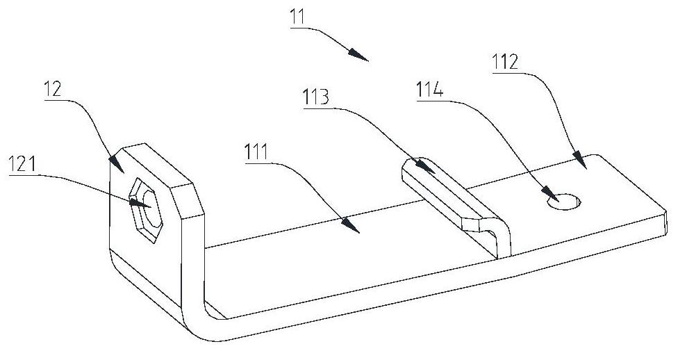
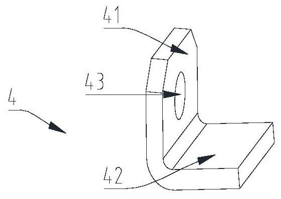
The invention provides a rail clamping device. The rail clamping device comprises a bearing assembly, wherein the bearing assembly comprises a bearing piece, a mounting piece, a jacking piece and a locking piece; the bearing piece is arranged at the bottom of a steel rail; a clamping part and a first mounting part are arranged on the bearing piece; the clamping part is arranged between the steel rail and the first mounting part and is clamped on one side of the steel rail; the mounting piece is connected with the bearing piece in an included angle manner; a second mounting part is arranged onthe mounting piece; one end part of the jacking piece is in contact with the other side of the steel rail; the other end part of the jacking piece is embedded into the second mounting part; and the locking piece is arranged on the jacking piece in a sleeving manner and is in contact with one side of the mounting piece. The rail clamping device provided by the invention is simple in structure; therail clamping device is fixed with the steel rail, so that related equipment including a mutual inductance coil, a sensor and the like is mounted; the mounting cost and the maintenance cost are low and the rail clamping device is applicable to a large number of application occasions.

Description

technical field [0001] The invention relates to the technical field of track structures, in particular to a rail clamp, a track and a method for installing the rail clamp. Background technique [0002] In the field of rail transit, it is often necessary to install mutual induction coils, sensors and other related equipment near the track. In order to control the installation accuracy, the rail clamp is generally fixed on the rail, and the mutual induction coil, sensors and other related equipment are installed on the rail clamp. superior. [0003] At present, existing rail clamps mainly include parts such as rail claws, step bolts, fastening nuts, locknuts, and magnetic steel frames. Among them, the track jaws are used in pairs, which are provided with opening slots for fastening the rails. The track jaws are connected together by step bolts. The U-shaped groove of the steel frame equipment is used to cooperate with the claws of the track. [0004] However, as far as the ...

Claims


Application Information

Patent Timeline
Patent Type & Authority Applications(China)
IPC IPC(8): F16M11/04F16M13/02
CPCF16M11/04F16M13/02
Inventor 韩冰高学锐刘克强李东义李美征
Owner CRRC QINGDAO SIFANG ROLLING STOCK RES INST
Learn More