
Vertical self-priming pump

A self-priming pump and vertical technology, applied in the field of vertical self-priming pumps, can solve the problems affecting the self-priming of the pump, the effect of gas-liquid mixing and separation, and reduce the working efficiency of the self-priming pump, and achieve the effect of rapid self-priming

Pending Publication Date: 2020-12-18
大连海特泵业有限公司
View PDF0 Cites 0 Cited by
  • Summary
  • Abstract
  • Description
  • Claims
  • Application Information

AI Technical Summary

Problems solved by technology

The existing self-priming pumps often have problems of poor sealing effect, poor gas-liquid mixing and separation, which affect the self-priming of the pump and reduce the working efficiency of the self-priming pump

Method used


Image

  • Vertical self-priming pump
  • Vertical self-priming pump
  • Vertical self-priming pump

Examples


Embodiment Construction

[0019] In order to make the structure and function of the present invention clearer, the technical solutions in the embodiments of the present invention will be clearly and completely described below in conjunction with the drawings in the embodiments of the present invention.

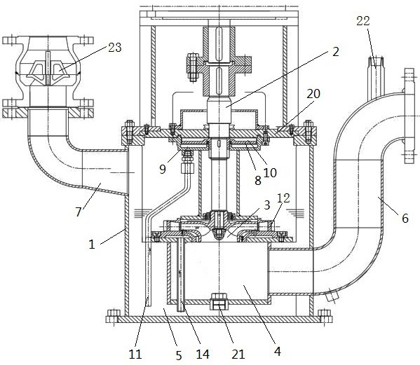
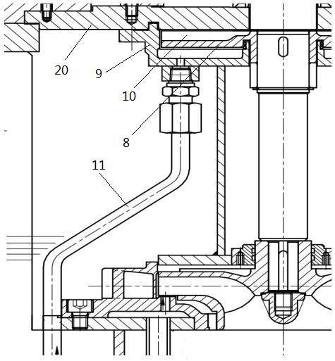
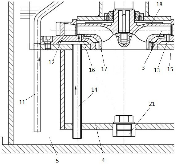
[0020] The vertical self-priming pump in the form of auxiliary impeller seal will install a set of auxiliary impellers on the shaft. The main function of the auxiliary impellers is to generate pressure opposite to the direction of the main impeller to achieve shaft sealing. The shaft seal does not require any pump during the entire service life of the pump. maintain. In the process of realizing self-priming, as the vacuum degree in the pump body increases, air intake will appear at the auxiliary impeller, which will affect the self-priming of the pump and reduce the working efficiency of the self-priming pump.

[0021] For the above problems, the present invention adopts the auxiliary impeller seal to ...


PUM


Abstract

The invention belongs to the technical field of self-priming pumps, and particularly relates to a vertical self-priming pump. The vertical self-priming pump comprises a pump body and a pump shaft arranged inside the pump body, wherein the pump shaft is driven by a motor, an impeller is arranged at the front end of the pump shaft, the interior of the pump body is divided into a water suction chamber and a water pressing chamber by the impeller, the water suction chamber communicates with a liquid inlet pipe, and the water pressing chamber communicates with a liquid outlet pipe. According to thevertical self-priming pump, rapid self-priming of the self-priming pump can be achieved.

Description

technical field [0001] The invention belongs to the technical field of self-priming pumps, and in particular relates to a vertical self-priming pump. Background technique [0002] When the self-priming pump is started for the first time, it needs to fill the pump chamber with clean water or the medium to be transported. After starting, through the high-speed rotation of the impeller, the liquid in the pump is mixed with air in the flow channel of the impeller to form a gas-liquid mixed state, and the gas-liquid mixture is in the impeller. Under the action, it enters the guide vane and the pump body, and realizes the rapid separation of gas and liquid in the pump body. The separated gas is discharged from the pump outlet or the exhaust pipe, and the liquid returns to the impeller channel from the return pipe to continue the gas-liquid mixing. The air in the inlet pipe of the pump is continuously discharged, and a vacuum is formed in the inlet pipe until the liquid completely ...

Claims


Application Information

Patent Timeline
Patent Type & Authority Applications(China)
IPC IPC(8): F04D9/02F04D1/00F04D29/22F04D29/42F04D29/44
CPCF04D9/02F04D1/00F04D29/2266F04D29/426F04D29/448
Inventor 王国全
Owner 大连海特泵业有限公司
Learn More