Concrete mixer

A technology of concrete mixer and mixing bucket, which is applied in the field of concrete, can solve problems such as concrete differences, and achieve the effect of increasing the range

Inactive Publication Date: 2020-12-11
刘荣添
View PDF12 Cites 0 Cited by
  • Summary
  • Abstract
  • Description
  • Claims
  • Application Information

AI Technical Summary

Problems solved by technology

[0004] The concrete material itself has a certain gravity, and there is a certain distance between the internal stirring rod and the inner wall, so that the internal concrete can have room to roll during the process of being stirred. When the rod is not in contact, it is easy to cause a certain difference between it and the concrete at the upper end

Method used


Image

  • Concrete mixer
  • Concrete mixer
  • Concrete mixer

Examples


Embodiment 1

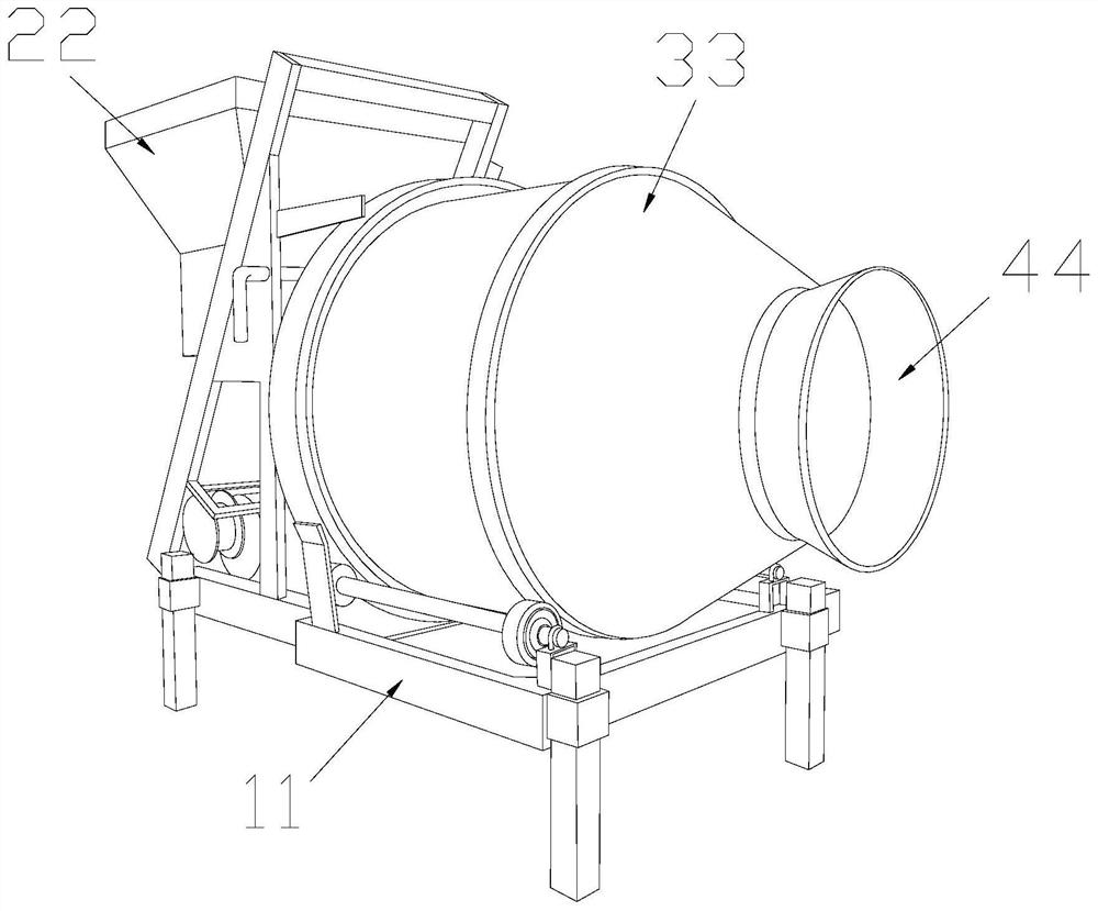
[0032] as attached figure 1 to the attached Image 6 shown:

[0033] The present invention provides a concrete mixer, the structure of which includes a support frame 11, an introduction bucket 22, a mixing bucket 33, and an outlet 44, the mixing bucket 33 is welded to the upper surface of the support frame 11, and the outlet 44 and the mixing bucket 33 are In an integrated structure, one end of the mixing bucket 33 away from the lead-out port 44 is connected with the lead-in bucket 22 .

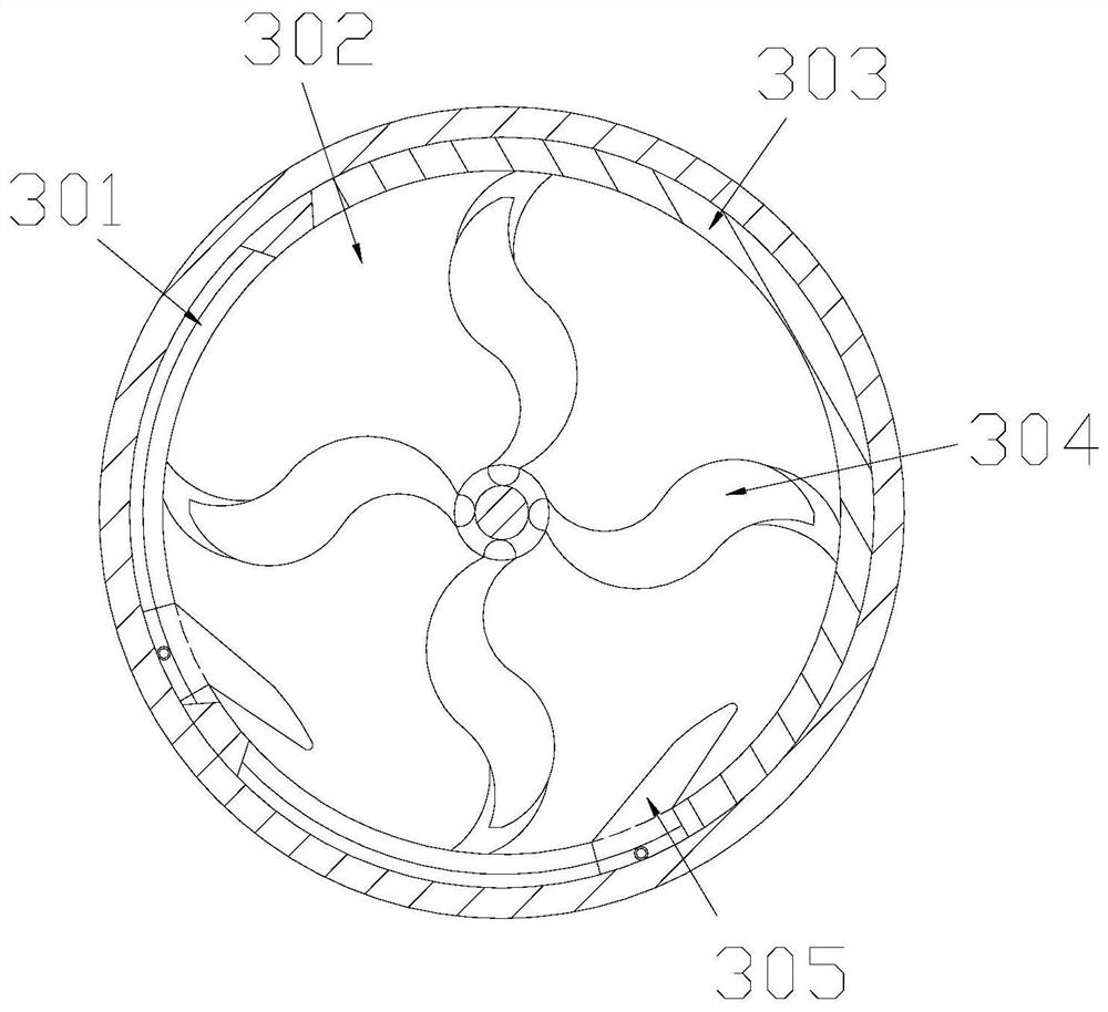
[0034] The mixing bucket 33 includes a ring channel 301, an inner grid 302, a limiting layer 303, a stirring rod 304, and a movable rocker 305. The movable rocker 305 is embedded in the ring channel 301 and is movably connected. The limiting layer 303 is welded, and the stirring rod 304 is installed inside the inner grid 302 .

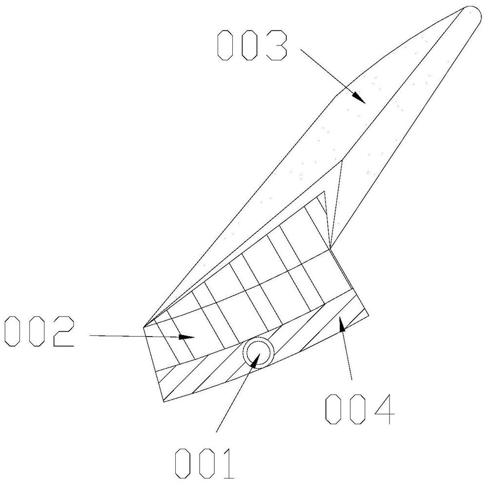
[0035] The movable rocker 305 includes a rolling ball 001, an extension core 002, an extension head 003, and a compliant block 004. The rolling ball 001 is embedde...

Embodiment 2

[0042] as attached Figure 7 to the attached Figure 9 shown:

[0043] The stirring rod 304 includes a front soft head e11, a main block e12, and a forward edge e13, the forward edge e13 and the main block e12 are an integrated structure, and the front soft head e11 is installed on the outer surface of the main block e12 , the main block e12 fixes the overall shape according to its own rigid force, the forward edge e13 extends to the inner range, and the front soft head e11 exerts a certain soft deformation on the object against which it collides.

[0044] The front soft head e11 includes a corner head w1, a soft strip w2, and a guide strip w3, the guide strip w3 is in contact with the soft strip w2, the corner head w1 is embedded in the soft strip w2, and the guide strip w3 is a curvilinear structure, the corner head w1 has a hard point on the outer layer, and the guide strip w3 bears the force from the outside to evenly separate them.

[0045] Wherein, the guide bar w3 incl...


PUM


Abstract

The invention discloses a concrete mixer which structurally comprises a supporting frame, a leading-in hopper, a mixing barrel and a leading-out opening; the mixing barrel is welded to the upper surface of the supporting frame; the leading-out opening and the mixing barrel are of an integrated structure; when a concrete material is placed in an inner grid to roll over, the material placed at the bottommost end can move along the track of a loop when a mixing rod rotates to limit the interior mounting range; when a movable warping plate reaches a certain position and concrete is accumulated atthe bottommost end, the movable warping plate can be pushed up along a stirring force and through a joint part and then returns to the original position, the whole range can be enlarged through circulation and an extended forward side, and the movable warping plate is more stable; when being extruded, the soft strip can extrude an external object through the corner head, so that the outer layer has a hard force point; and when the front soft head bears an external force, the end head has a certain buffer effect when the front soft head integrally bears hard force to abut against the external object.

Description

technical field [0001] The invention belongs to the field of concrete, and more particularly, relates to a concrete mixer. Background technique [0002] The concrete mixer needs to first import sand, gravel, cement and other materials in proportion, and then roll the materials through the rotation of the materials in the drum, so that the materials can be evenly mixed together, and then output the materials for use. [0003] Based on the above-mentioned inventor's discovery, the existing concrete mixer mainly has the following deficiencies, such as: [0004] The concrete material itself has a certain gravity, and there is a certain distance between the inner mixing rod and the inner wall, so that the inner concrete can have a tumbling space during the mixing process. When the rod is out of contact, it is easier to cause a certain difference between it and the concrete at the upper end. [0005] Therefore, there is a need to propose a concrete mixer. SUMMARY OF THE INVENT...

Claims


Application Information

Patent Timeline
Patent Type & Authority Applications(China)
IPC IPC(8): B28C5/20B28C5/24
CPCB28C5/2045B28C5/24
Inventor 刘荣添
Owner 刘荣添
Why Eureka
Try Eureka