
Sealing structure of horizontal rotary pyrolysis kiln

A sealed structure, pyrolysis kiln technology, used in rotary drum furnaces, lighting and heating equipment, furnaces, etc., can solve the problems of short service life, air leakage of flexible connectors, short service life of flexible connectors, etc. performance, improve service life

Pending Publication Date: 2020-12-08
HENAN DRAGON INTO COAL TECH CO LTD +1
View PDF1 Cites 2 Cited by
  • Summary
  • Abstract
  • Description
  • Claims
  • Application Information

AI Technical Summary

Problems solved by technology

In the prior art, the fish scale seal technology is used to seal the feeding cover, but this fish scale seal cannot completely seal the gas in the field of coal pyrolysis, and there are major safety hazards; there is also a method of using flexible connection and rubber seal for feeding However, although this method can achieve complete sealing, the durability of the flexible sealing material is limited and the service life is short
[0003] The patent of the rotary sealing mechanism with the publication number CN106482506A, although a labyrinth-type dust-retaining and heat-insulating wall is set in front of the "flexible connecting body", but because the labyrinth-type dust-retaining and heat-insulating wall is in a high-temperature environment for a long time, the "flexible connecting body" will inevitably In a relatively high temperature environment, there is a problem of short service life of the flexible connecting body in actual production, and in some cases, even air leakage of the flexible connecting body may occur, which seriously affects the sealing effect of the sealing mechanism

Method used


Image

  • Sealing structure of horizontal rotary pyrolysis kiln
  • Sealing structure of horizontal rotary pyrolysis kiln
  • Sealing structure of horizontal rotary pyrolysis kiln

Examples


Embodiment 1

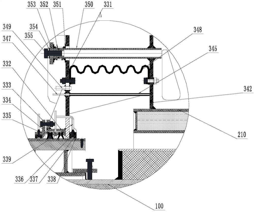
[0051] see figure 1 and figure 2 , this embodiment provides a sealing structure for a horizontal rotary pyrolysis kiln. It includes: a horizontal rotary pyrolysis kiln main body 100 , a kiln tail 110 , a kiln tail cover 200 , and a rotary sealing structure 300 . Wherein, a discharge port 400 for solid material after pyrolysis is provided under the kiln tail cover 200, and a pyrolysis gas outlet 500 is provided at the center of the end face of the kiln tail. The heat preservation layer 120 of the horizontal rotary pyrolysis kiln tail cover is arranged on the outer periphery of the kiln tail cover 200 . A kiln tail outer insulation layer 310 is arranged on the outer periphery of the kiln tail 110 .

[0052] refer to figure 1 As shown, a support frame 320 is fixedly arranged on the outer periphery of the kiln tail 110 , and the support frame 320 rotates synchronously with the kiln tail 110 . The support frame 320 includes the support frame inner ring 321 arranged on the out...

Embodiment 2

[0079] refer to image 3 with Figure 4 As shown, the difference from Embodiment 1 is that Embodiment 2 is based on Embodiment 1. In order to shorten the axial length of the movable heat-insulation sealing ring 345 and the flexible sealing mechanism 348, respectively in the vertical ring of the rotary sealing mechanism A grooved ring is added between the plate one 331 and the kiln tail vertical annular plate two 342.

[0080] Correspondingly, a left annular groove 340, a left packing 341, a right annular groove 343, a right packing 344 and a friction ring 346 of the movable heat insulation sealing ring are added, and the left annular groove 340 is fixed to the vertical annular plate 331 of the rotary sealing mechanism. One end of the left annular groove 340 away from the vertical annular plate one 331 of the rotary sealing mechanism is fixedly connected with a flexible sealing mechanism 348 .

[0081] A right annular groove 343 is connected to the end of the kiln tail vertic...


PUM


Abstract

The invention provides a sealing structure of a horizontal rotary pyrolysis kiln, and relates to sealing technology of a thermal-state sealing cover of a horizontal rotary kiln. By arranging a movableheat insulation sealing ring, a heat insulation cavity is formed between the movable heat insulation sealing ring and a flexible sealing mechanism, the heat insulation cavity can effectively block heat dissipated by a kiln tail cover and a kiln tail, and the environment temperature of the flexible sealing mechanism in the heat insulation cavity is effectively reduced, so that the service life ofthe flexible sealing mechanism can be prolonged, and the effectiveness of sealing is ensured.

Description

technical field [0001] The invention relates to a sealing technology for a thermal sealing cover of a horizontal rotary kiln, in particular to a sealing structure of a horizontal rotary pyrolysis kiln. Background technique [0002] In the coal pyrolysis field of horizontal rotary kiln, the sealing of the feeding hood is one of the most critical safety and environmental protection technologies. In the prior art, the fish scale seal technology is used to seal the feeding cover, but this fish scale seal cannot completely seal the gas in the field of coal pyrolysis, and there are major safety hazards; there is also a method of using flexible connection and rubber seal for feeding However, although this method can achieve complete sealing, the durability of the flexible sealing material is limited and the service life is short. [0003] The patent of the rotary sealing mechanism with the publication number CN106482506A, although a labyrinth-type dust-retaining and heat-insulatin...

Claims


Application Information

Patent Timeline
Patent Type & Authority Applications(China)
IPC IPC(8): F27B7/24
CPCF27B7/24F27M2003/14F27D99/0073F27B7/22F27B7/20
Inventor 朱书成李金峰赵博王永兴王希彬
Owner HENAN DRAGON INTO COAL TECH CO LTD
Learn More