
Bridge anti-falling beam device capable of balancing transverse bending moment

A technology of anti-drop beam and bending moment, applied in the direction of bridges, bridge parts, bridge construction, etc., to improve stability, improve the effect of anti-drop beam, and reduce costs

Active Publication Date: 2020-12-08
河北振创电子科技有限公司
View PDF16 Cites 4 Cited by
  • Summary
  • Abstract
  • Description
  • Claims
  • Application Information

AI Technical Summary

Problems solved by technology

[0003] Most of the current anti-fall beam structures are arranged on both sides of the main girder. When the main girder is subjected to horizontal and vertical earthquake excitations, it may also be subjected to bending moments at the supporting parts of the pier. At this time, the anti-fall beam devices located on both sides of the main girder The direction of the force is opposite, often resulting in only the anti-fall beam device on the side of the main beam can be used to prevent the beam from falling, and the effect of preventing the beam from falling cannot be well exerted

Method used


Image

  • Bridge anti-falling beam device capable of balancing transverse bending moment
  • Bridge anti-falling beam device capable of balancing transverse bending moment
  • Bridge anti-falling beam device capable of balancing transverse bending moment

Examples


Embodiment Construction

[0025] Hereinafter, an embodiment of the present invention by certain specific examples, a skilled person may be described in the present specification easily understand other advantages and effects of the present invention. The present invention can also be implemented or applied by other embodiments, and various details in this specification may also be based on different viewpoints and applications without departing from the spirit of the invention. It should be noted that the illustrations provided in the following examples will be described only by way of illustration, and in the case of unlamating, the following embodiments and embodiments may be combined with each other.

[0026] The drawings are for exemplary description, which is intended to be schematic diagrams, rather than experiencing, is not understood to limit the invention; in order to better illustrate an embodiment of the invention, there will be omitted, To zoom in, it does not represent the size of the actual p...


PUM


Abstract

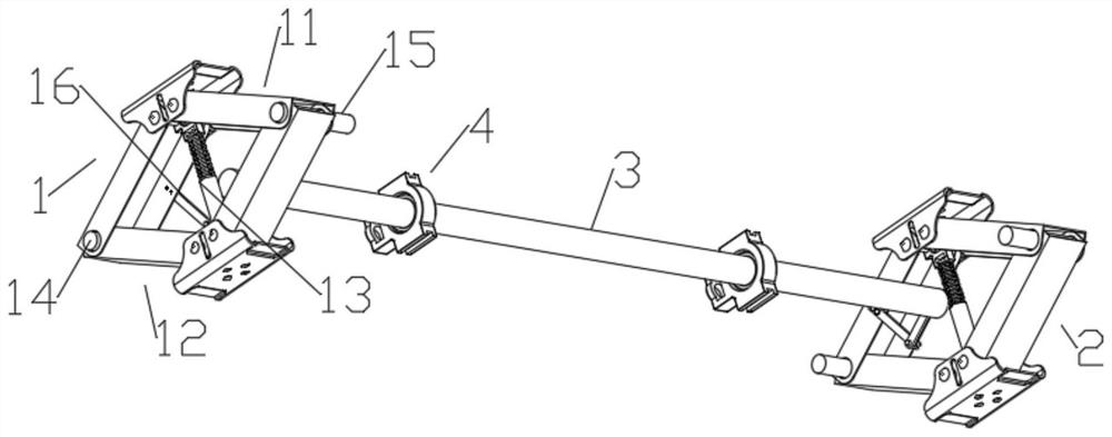
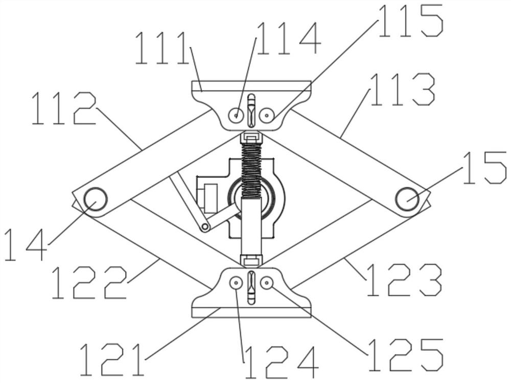
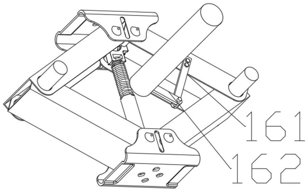
The invention discloses a bridge anti-falling beam device capable of balancing transverse bending moment, and belongs to the technical field of building bridges. The bridge anti-falling beam device comprises a first longitudinal anti-falling beam assembly and a second longitudinal anti-falling beam assembly which are correspondingly positioned at the two sides of main beams. The first longitudinalanti-falling beam assembly and the second longitudinal anti-falling beam assembly are connected with a balance rod, the balance rod is located in a gap between the two adjacent main beams, installation bases are fixedly arranged on the end faces of the main beams, and the balance rod is rotationally connected with the main beams through the installation bases. When the two main beams generate displacement in the longitudinal direction, upper compression devices and lower compression devices get close to each other in the vertical direction, and the upper compression devices act on the balancerod through connecting rod assemblies to enable the balance rod to rotate by a certain angle. According to the bridge anti-falling beam device, through the linkage effect of the first longitudinal anti-falling beam assembly and the second longitudinal anti-falling beam assembly at the two sides of the main beams, beam falling can be effectively prevented.

Description

Technical field [0001] The present invention belongs to the technical field of building bridges, particularly the anti-drop bridge beam device relates to an equilibrium lateral bending moment. Background technique [0002] When the bridge suffered a strong earthquake, the bridge will withstand great loads in an instant, resulting in a larger displacement, displacement of more than shelved because of insufficient length or intensity can cause stop off beam, off the beam will bring irreparable beam the heavy losses. Anti-drop beam structure which is used for seismic structural bridge, measures to prevent the connection structure of the beam falling or disengaged. [0003] Currently most of the fall preventing a beam structure arranged on both sides of the main beam, the main beam when subjected to horizontal and vertical seismic excitation, there may be moments pier support point, this time anti-drop means located at both sides of the main beam of the beam receiving the opposite di...

Claims


Application Information

Patent Timeline
Patent Type & Authority Applications(China)
IPC IPC(8): F16F15/02E01D19/00
CPCE01D19/00F16F15/02
Inventor 何先龙孙得璋马斌唐芳宗贾行建
Owner 河北振创电子科技有限公司
Learn More