Refrigeration house wallboard convenient to assemble
A technology for wall panels and cold storage, applied in building components, building insulation materials, buildings, etc., can solve problems such as poor structural stability, poor sealing, and inability to perform fast connections, achieving quick disassembly and ensuring the stability of splicing
- Summary
- Abstract
- Description
- Claims
- Application Information
AI Technical Summary
Problems solved by technology
Method used
Image
Examples
Embodiment 1
[0028] Example 1 as Figure 1-2 As shown, this easy-to-assemble cold storage wall panel includes a first wall panel 1 and a second wall panel 2, the first wall panel 1 is located on the left side of the second wall panel 2, and both sides are provided with connecting grooves, The groove walls of the two connection grooves are all provided with splicing grooves 3, and the upper and lower sides of the splicing groove 3 are all provided with limit grooves, and elastic limit mechanisms are arranged in the limit grooves, and both sides of the second wallboard 2 are fixedly equipped with Connecting plate 4, connecting plate 4 contacts and connects with the groove wall of connecting groove, and the other side of two connecting plates 4 is all fixedly provided with splicing block 5, and splicing block 5 contacts and connects with the groove wall of splicing groove, and connecting plate 4 and The connecting groove, the splicing block 5 and the splicing groove 3 ensure the connection ti...
Embodiment 2
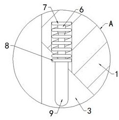
[0029] Embodiment 2 is on the basis of embodiment 1 such as figure 1 and 3 As shown, its elastic limit mechanism includes a telescopic rod 6 and a first spring 7, the groove wall of the limit groove is fixedly connected with the telescopic rod 6 and the first spring 7, the telescopic rod 6 and the first spring 7 are socketed, and the bottom A fixed plate 8 is fixed together, the bottom of the fixed plate 8 is fixed with an insertion rod 9, the insertion rod 9 is connected with the groove wall of the ejection groove, and the fixed plate 8 is set to the first spring 7, the telescopic rod 6 and the insertion rod 9 For fixed support.
Embodiment 3
[0030] Embodiment 3 is such as on the basis of embodiment 1 figure 1 , Figure 4 and Figure 5 As shown, its ejector mechanism includes a horizontal plate 10, and both ends of the cavity are longitudinally fixed with support rods 11. The horizontal plate 10 is fixedly socketed with two support rods 11, and the rod walls of the two support rods 11 are up and down. Both ends are slidingly sleeved with a pressure plate 12, and are sleeved with a second spring 13. The two ends of the second spring 13 are fixedly connected with the cavity and the pressure plate 12 respectively, and the two ends of the side wall of the pressure plate 12 are fixed with a push rod 14. , the ejector rod 14 passes through the ejection groove and is in contact with the bottom of the rod wall of the insertion rod 9, and the ejector rod 14 is set to facilitate pushing the insertion rod 9 out of the ejection groove.
PUM
 Abstract
Description
Claims
Application Information
 - R&D
- Intellectual Property
- Life Sciences
- Materials
- Tech Scout
- Unparalleled Data Quality
- Higher Quality Content
- 60% Fewer Hallucinations
Browse by: Latest US Patents, China's latest patents, Technical Efficacy Thesaurus, Application Domain, Technology Topic, Popular Technical Reports.
© 2025 PatSnap. All rights reserved.Legal|Privacy policy|Modern Slavery Act Transparency Statement|Sitemap|About US| Contact US: help@patsnap.com


