Multi-head laser master-slave control method

A control method and laser technology, applied in laser welding equipment, manufacturing tools, welding equipment, etc., can solve the problems of increased equipment loss, decreased marking efficiency, slow laser marking speed, etc., and achieve the effect of improving marking efficiency

Inactive Publication Date: 2020-12-08
苏州海力士光电科技有限公司
View PDF6 Cites 2 Cited by
  • Summary
  • Abstract
  • Description
  • Claims
  • Application Information

AI Technical Summary

Problems solved by technology

[0003] In the food packaging industry, laser online flying marking technology is also widely used, but in the actual marking process of food packaging bags, the transmission speed of packaged food on the assembly line is relatively fast, while the speed of laser marking is relatively slow , usually multiple laser devices with the same efficiency are configured on the assembly line to adapt to the assembly line. There is a simple multiplication relationship between laser equipment, and its overall efficiency depends on the one with the slowest marking efficiency, that is, assuming that the marking efficiency of a laser equipment decreases due to factors such as power attenuation, then the equipment that makes the above power attenuation Withdrawal from use, or all other equipment is also lowered together to ensure that the equipment will not miss marking in batches, or use high-efficiency laser equipment and low-efficiency laser equipment together, but it does not make much sense, because high-efficiency equipment must Only by reducing the efficiency to low-efficiency equipment can we ensure that low-efficiency equipment will not miss marking in batches because the efficiency cannot keep up. If the above method is used, the efficiency of high-efficiency laser equipment will be reduced and the loss of equipment will be increased; for Therefore, this application proposes a multi-head laser master-slave control method

Method used


Image

  • Multi-head laser master-slave control method

Examples


Embodiment Construction

[0021] In order to make the object, technical solution and advantages of the present invention clearer, the present invention will be further described in detail below in combination with specific embodiments and with reference to the accompanying drawings. It should be understood that these descriptions are exemplary only, and are not intended to limit the scope of the present invention. Also, in the following description, descriptions of well-known structures and techniques are omitted to avoid unnecessarily obscuring the concept of the present invention.

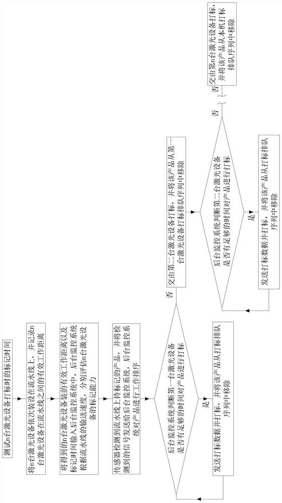
[0022] Such as figure 1 As shown, a kind of multi-head laser master-slave control method proposed by the present invention comprises the following specific steps:

[0023] S1. Test the marking time of n sets of laser equipment respectively. The marking time of n sets is respectively marked as t1, t2...tn; among them, the n sets of laser equipment are recorded as J1, J2...Jn in turn;

[0024] S2. Install J1, J2...Jn on t...


PUM


Abstract

The invention discloses a multi-head laser master-slave control method, and the method comprises the following specific steps of S1, respectively testing the marking time of n pieces of laser equipment during marking, and sequentially recording the n pieces of laser equipment as J1, J2... Jn; installing J1, J2...Jn on an assembly line in sequence along the conveying direction of the assembly line,and recording the effective working distance of the above equipment on the assembly line; step S2, inputting measured data into a background monitoring system, and according to the conveying speed ofthe assembly line, respectively evaluating the marking capability of J1, J2...Jn; step S3, detecting products on the assembly line by a sensor and sending a detected signal to the background monitoring system; performing work sorting on the products in sequence by the background monitoring system; and S5, sequentially judging whether J1, J2... Jn have enough time to mark the products by the background monitoring system or not. According to the multi-head laser master-slave control method provided by the invention, marking tasks can be allocated to each laser equipment according to the markingcapability of each laser equipment, and the marking efficiency of the products is greatly improved.

Description

technical field [0001] The invention relates to the technical field of laser marking, in particular to a multi-head laser master-slave control method. Background technique [0002] With the popularization of the application of laser technology, more and more products are marked by laser technology; the basic principle of laser marking technology is to realize graphic printing through laser marking machine, which is to generate high-energy continuous laser beam by laser generator . When the laser acts on the printing material, the atoms in the ground state transition to a higher energy state; the atoms in the higher energy state are unstable and will quickly return to the ground state. When the atoms return to the ground state, they will be in the form of photons or quantum The extra energy is released and converted from light energy to heat energy, which instantly melts or even vaporizes the surface material to form a graphic mark; [0003] In the food packaging industry, ...

Claims


Application Information

Patent Timeline
Patent Type & Authority Applications(China)
IPC IPC(8): B23K26/362B23K26/067B23K26/70
CPCB23K26/0673B23K26/362B23K26/702B23K26/707
Inventor 王栋董习洪鹏程黄伟陈田平
Owner 苏州海力士光电科技有限公司
Why Eureka
Try Eureka