Combined drill

A combination drill bit and drill bit technology, which is applied in the direction of drill bit, drilling equipment, earthwork drilling, etc., can solve the problems of high resistance, inability to drill, low hole formation rate, poor quality, etc., to solve the problem of collapsed holes and drill sticking, and to facilitate production , the effect of simple structure

Inactive Publication Date: 2020-12-01
郑乃国
View PDF0 Cites 0 Cited by
  • Summary
  • Abstract
  • Description
  • Claims
  • Application Information

AI Technical Summary

Problems solved by technology

[0002] When using the existing common drill bit in the process of drilling into the stratum to form a hole, problems such as hole collapse, drill sticking, low hole formation rate, poor quality, and high resistance cannot be drilled often occur. In order to solve this problem, a new technology was invented. A sleeve drill bit with a combined function design, this drill bit:

Method used


Image

  • Combined drill
  • Combined drill
  • Combined drill

Examples


Embodiment 1

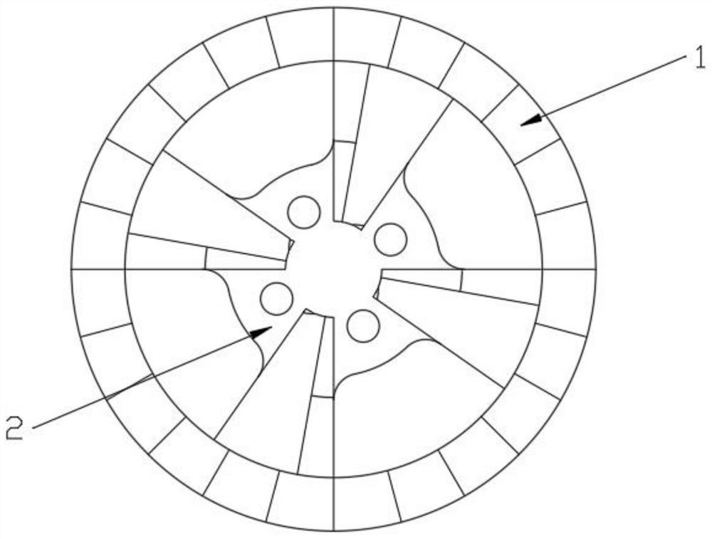
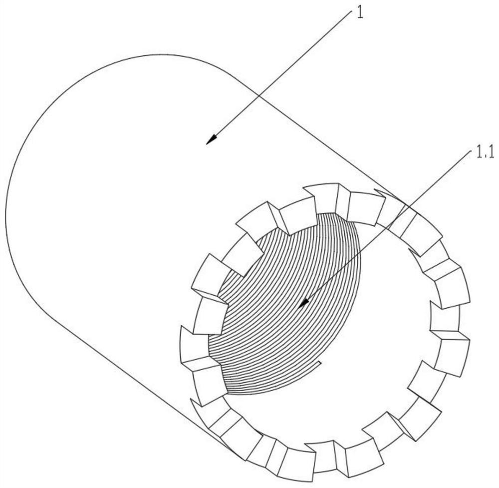
[0019] combined with figure 1 , 3 , 4, a combination drill bit, comprising a first drill bit 1, a second drill bit 2, the first drill bit 1 is cylindrical, its interior is coaxially provided with a second drill bit 2 connected thereto, the first drill bit 1 and A plurality of drainage grooves 2.4 are arranged between the second drill bits 2 for outputting slag flow from the inside of the drill bits, and the drainage grooves 2.4 are evenly arranged on the outer ring of the second drill bit 2 along the axial direction of the second drill bit 2 Above, the middle part of the second drill bit 2 is provided with a through-hole 2.5 for inputting water flow, and the head of the second drill bit 2 is arranged at a certain distance away from the axial end of the head of the first drill bit 1. The first drill bit 1 is flush with the tail of the second drill bit 2, and the second drill bit 2 is connected with the drill rod.

[0020] As a preferred implementation of this embodiment, the ...

Embodiment 2

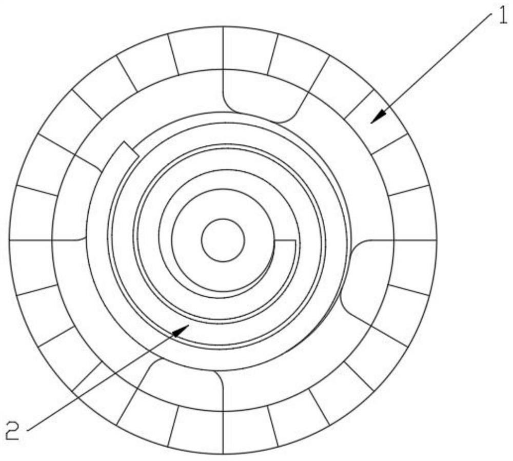
[0023] combined with figure 2 , 3 , 5, a kind of combination drill bit, comprise first drill bit 1, second drill bit 2, described first drill bit 1 is cylindrical shape, and its inside is coaxially provided with and connects second drill bit 2, described first drill bit 1 and A plurality of drainage grooves 2.4 are arranged between the second drill bits 2 for outputting slag flow from the inside of the drill bits, and the drainage grooves 2.4 are evenly arranged on the outer ring of the second drill bit 2 along the axial direction of the second drill bit 2 Above, the middle part of the second drill bit 2 is provided with a through-hole 2.5 for inputting water flow, and the head of the second drill bit 2 is arranged at a certain distance away from the axial end of the head of the first drill bit 1. The first drill bit 1 is flush with the tail of the second drill bit 2, and the second drill bit 2 is connected with the drill rod.

[0024] As a preferred implementation of this ...


PUM


Abstract

The invention discloses a combined drill. The combined drill comprises a first drill bit and a second drill bit, wherein the first drill bit is cylindrical; the second drill bit connected with the first drill bit is coaxially arranged in the first drill bit; a plurality of drainage grooves used for outputting slag flow from the interiors of the drill bits are formed between the first drill bit andthe second drill bit; the drainage grooves are evenly formed in the outer ring of the second drill bit in the axial direction of the second drill bit; a through hole used for inputting water flow isformed in the middle of the second drill bit; the head of the second drill bit is arranged at the position, close to one end of the head of the first drill bit by a certain distance in the axial direction; the tail of the first drill bit is flush with the tail of the second drill bit; and the second drill bit is connected with a drill rod. Through cooperative work of two different drill bit functional combinations and change of drill bit cutting and de-slagging ways, smoothness and completeness of the inner wall face of a drill hole are guaranteed, the hole forming rate of the drill hole is increased, the length of the drill hole is increased, and the problems of hole collapse and drill jamming in the stratum drilling process are effectively solved.

Description

technical field [0001] The invention relates to the technical field of drilling tools for formation drilling, in particular to a combined drill bit. Background technique [0002] When using the existing common drill bit in the process of drilling into the stratum to form a hole, there are often problems such as hole collapse, drill sticking, low hole formation rate, poor quality, and high resistance that cannot be drilled. In order to solve this problem, a new technology was invented. A sleeve drill bit with a combined function design, this drill bit: [0003] 1. The slag discharge water flows out from the annular space between the inner and outer drill bits of the combined drill bit, thereby reducing the disturbance to the formation, reducing the drilling resistance and damage to the hole wall, ensuring the smooth and complete hole wall, and preventing hole collapse stuck drill; [0004] 2. Use the external core bit to form holes and retain walls, and use the internal con...

Claims


Application Information

Patent Timeline
Patent Type & Authority Applications(China)
IPC IPC(8): E21B10/00E21B10/60E21B10/54E21B10/43E21B25/00
CPCE21B10/00E21B10/43E21B10/54E21B10/60E21B25/00
Inventor 郑乃国
Owner 郑乃国
Why Eureka
Try Eureka