
Electronic cigarette with optimised vaporisation

A technology for electronic cigarettes and capsules, which is applied in the directions of tobacco, pipes, electrical components, etc., can solve the problems that the mesh can not give satisfactory results, the size of vapor droplets is small, and it is difficult to achieve vapor flow.

Pending Publication Date: 2020-11-27
JT INT SA
View PDF12 Cites 3 Cited by
  • Summary
  • Abstract
  • Description
  • Claims
  • Application Information

AI Technical Summary

Problems solved by technology

[0006] However, since the desired vapor droplet size in aerosols is very small, the mesh still does not give satisfactory results
Even if the opening in the mesh is reduced, the associated flow restriction increases and satisfactory vapor flow from the nozzle remains difficult to achieve

Method used


Image

  • Electronic cigarette with optimised vaporisation
  • Electronic cigarette with optimised vaporisation
  • Electronic cigarette with optimised vaporisation

Examples


example 1

[0069] Diameter: 0.4mm

[0070] Resistance length: 70mm

[0071] Resistance: 0.294Ω

[0072] Total effective length: 68mm

[0073] Pitch: 0.7mm

[0074] Heating coil height: 4.75mm

[0075] Total effective surface: 85.45mm2

[0076] Power density: 0.187W / mm2

[0077] Heated convection: 1040W / m2K

[0078] Height of fluid transfer element: 5.8mm

[0079] Additionally, the liquid inlet to the fluid transfer element 38 is enlarged in the axial direction of the fluid transfer element 38 in order to provide a sufficient supply of liquid along the entire length of the heater element 36 .

[0080] However, the first exemplary balloon provided unsatisfactory results, although the liquid supply to the heater element 36 and saturated fluid transfer element 38 was adequate and evenly distributed. The coils exhibited an inconsistent heating curve where the lower part of the heating coil only reached 300K while the upper part of the coil reached about 900K. Since the total measurab...

example 2

[0091] Diameter: between 0.226 and 0.3mm, preferably 0.254mm

[0092] Resistance length: 26.92mm

[0093] Resistance: between 0.291 and 0.295Ω

[0094] Total effective length: 26.09mm

[0095] Pitch: between 0.5-1.0mm, preferably 1.0mm

[0096] Heating coil height: between 2.4-3.2mm

[0097] Total effective surface: 20.82mm2

[0098] Power density: between 1.152 and 2.319Watt / mm2, preferably 1.152Watt / mm2

[0099] Heated convection: at 5000 and 7000W / m 2 Between K, preferably about 6000W / m 2 K,W / m2K

[0100] Height of the fluid transfer element: between 4.5 and 6.5mm, preferably 5.8mm mm

[0101] Capillary height of the fluid transfer element: equal to or exceed the actual height of the fluid transfer element

[0102] Seal Type: It was shown that a non-circular seal with a height greater than width is most beneficial in maintaining negative pressure in the liquid reservoir 32 .

[0103] The optimum pitch of the windings was found to be within a preferred range betwee...


PUM


Abstract

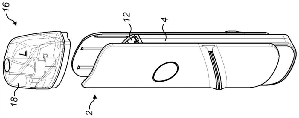
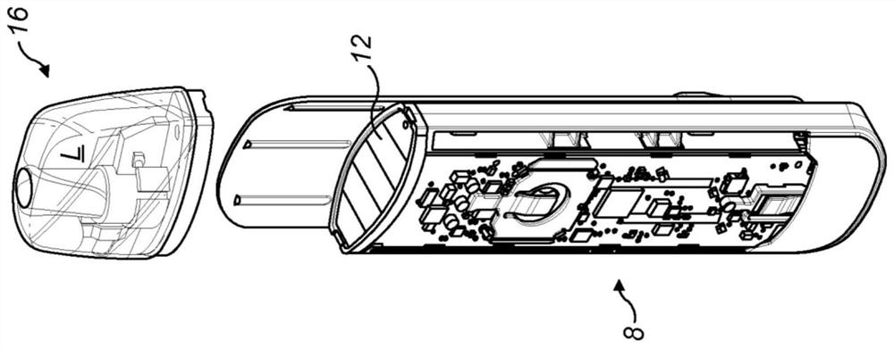
A capsule (16) for an electronic cigarette is disclosed, the capsule having a first end for engaging with an electronic cigarette device and a second end configured as a mouthpiece portion (28) havinga vapor outlet, the capsule further comprising: a liquid store (32) configured to contain a liquid L to be vaporized, a vaporizing unit (34) comprising a heater (36) and a fluid transfer element (38), the vaporizing unit being arranged within a vaporizing chamber (30), a main vapor channel (24) extending from the vaporizing chamber to the vapor outlet in the mouthpiece, and a housing enclosing the liquid store and the vaporizing unit, wherein the housing comprises an inner housing (18a) and an outer housing (18b) that are assembled together, wherein the liquid store (32) is located in a voidin-between the inner housing and the outer housing, wherein a seal (50) is provided between the inner housing and the outer housing, and wherein the seal has a cross-sectional shape having a cross-sectional height hs that is larger than a cross-sectional width Ws.

Description

technical field [0001] The present invention relates to personal vaporizing devices, such as electronic cigarettes. In particular, the present invention relates to an electronic cigarette and a disposable capsule therefor. Background technique [0002] E-cigarettes are an alternative to regular cigarettes. Instead of producing combustion aerosols, e-cigarettes vaporize a liquid that can be inhaled by the user. Liquids typically include aerosol-forming substances such as glycerin or propylene glycol which generate vapors. Other common substances in the liquid are nicotine and a variety of different flavors. [0003] Electronic cigarette is a hand-held inhaler system, including a nozzle part, a liquid reservoir, and a power supply unit. Vaporization is achieved by a vaporizer or heater unit which typically includes a heating element in the form of a heating coil and a fluid transfer element. Vaporization occurs as the heater heats the liquid in the wick until the liquid c...

Claims


Application Information

Patent Timeline
Patent Type & Authority Applications(China)
IPC IPC(8): A24F40/42A24F40/10A24F40/40A24F40/44A24F40/46
CPCA24F40/44A24F40/10A24F40/46A24F40/40A24F40/42A24F40/485A24F7/00H05B3/748A24F40/48H05B1/0297H05B3/42
Inventor 赫尔曼·海玛凯尔·阿代尔
Owner JT INT SA
Learn More