Multi-rod type radar edge block antenna overturning and locking mechanism

A locking mechanism and side block technology, applied in the directions of antennas, antenna parts, antenna supports/installation devices, etc., can solve the problems of high space size requirements, achieve high space utilization, easy installation and local maintenance, movement High precision and stability effect

Active Publication Date: 2020-11-27
CHINA ELECTRONIC TECH GRP CORP NO 38 RES INST
View PDF11 Cites 0 Cited by
  • Summary
  • Abstract
  • Description
  • Claims
  • Application Information

AI Technical Summary

Problems solved by technology

[0005] The technical problem to be solved by the present invention is: how to solve the problem that the hinge point arrangement of the traditional side block array flipping mechanism has a high requirement on the space size, and provides a multi-rod radar side block antenna flip locking mechanism

Method used


Image

  • Multi-rod type radar edge block antenna overturning and locking mechanism
  • Multi-rod type radar edge block antenna overturning and locking mechanism
  • Multi-rod type radar edge block antenna overturning and locking mechanism

Examples


Embodiment 1

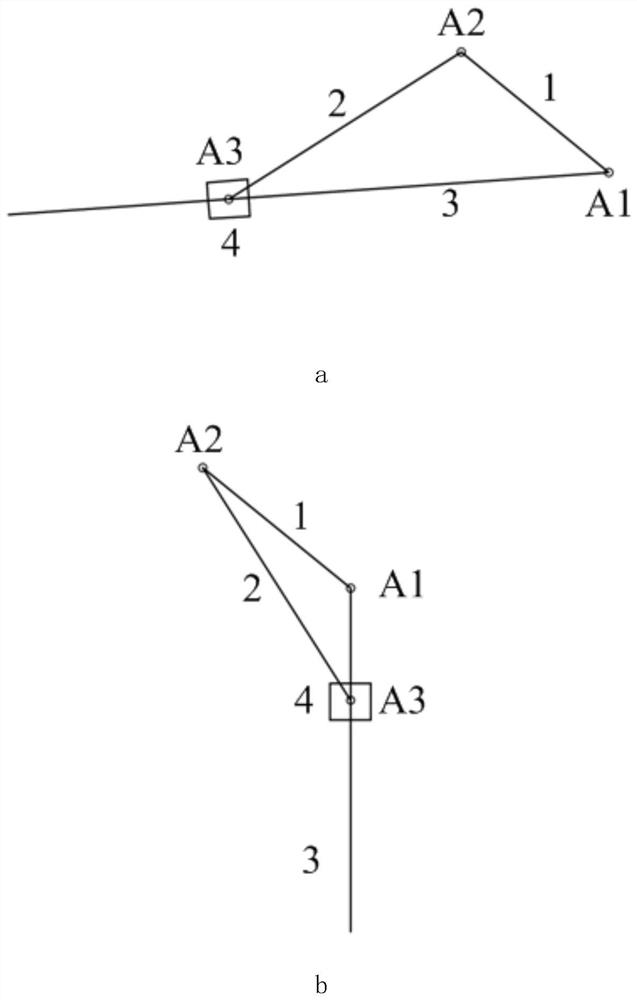
[0023] This embodiment provides a technical solution: a multi-rod radar side block antenna flip locking mechanism, including antenna back frame, side block frame, flip oil cylinder, follower rod, locking positioning part, support rod, the side The block frame is rotatably connected to the antenna back frame, one end of the flip cylinder is rotatably connected to the antenna back frame, the other end is rotatably connected to the side block frame, and one end of the follower rod is rotatably connected to the side block frame connected, the other end is rotatably connected to the support rod, and one end of the support rod is rotatably connected to the side frame. In the working state, the side frame is parallel to the antenna back frame. In the transport state, the side block The skeleton is perpendicular to the antenna back frame, and the other end of the support rod is locked by the locking positioning member to locate the position of the side block skeleton.

[0024] The sid...

Embodiment 2

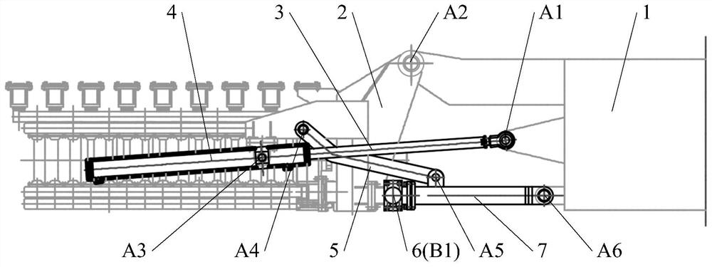
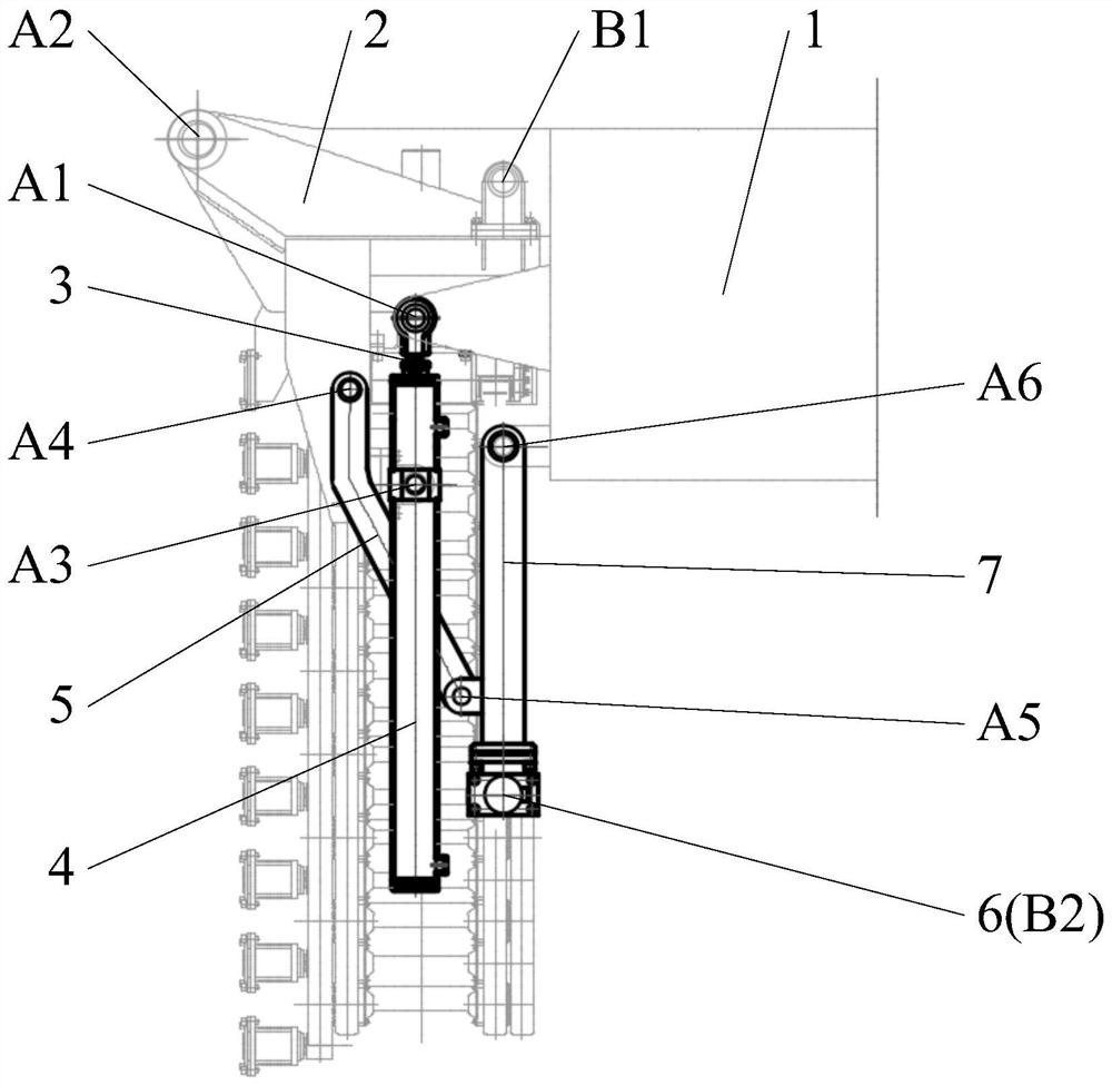
[0032] like figure 1 , figure 2 As shown, the flip locking mechanism of the multi-rod radar side block antenna includes an antenna back frame 1, a side block frame 2, a flip cylinder (including a flip cylinder rod 3 and a flip cylinder body 4), a follower rod 5, Hydraulic latch 6, support rod 7, hinge points A1-A6, etc. The antenna back frame 1 is the normal reference frame of the entire radar antenna front, the side block frame 2 is used to carry the side block antenna, is hinged with the antenna back frame 1 through the hinge point A2, and is arranged on one side of the antenna back frame 1. sideways or symmetrically arranged on both sides of the antenna back frame 1 . The turning cylinder is used to provide turning driving force, wherein the turning cylinder rod 3 is hinged with the antenna back frame 1 through the hinge point A1, and the turning cylinder body 4 is hinged with the side block frame 2 through the hinge point A3; the follower rod 5. One end is hinged to th...


PUM


Abstract

The invention discloses a multi-rod type radar edge block antenna overturning and locking mechanism, and belongs to the technical field of antenna overturning and locking. The mechanism comprises an antenna back frame, an edge block framework, an overturning oil cylinder, a follow-up rod, a locking positioning piece and a supporting rod, wherein the edge block framework is rotatably connected withthe antenna back frame, one end of the overturning oil cylinder is rotatably connected with the antenna back frame, the other end of the overturning oil cylinder is rotatably connected with the edgeblock framework, and one end of the follow-up rod is rotatably connected with the edge block framework. According to the invention, a slider-crank mechanism with the slider as a driving piece is adopted to complete the overturning action of the edge block antenna, and a four-bar mechanism is adopted to complete the overturning locking of a working state and a transportation state, so that the movement precision and stability are high; the positions of a connecting rod and a hinge point have design adjustability in space, the spatial positions of the connecting rod and the hinge point can be adjusted according to actual layout requirements, and the space utilization rate is high; and one locking bolt is used for completing overturning locking in the working state and the transportation state, the structure is simple, and the installation and local maintenance are easy.

Description

technical field [0001] The invention relates to the technical field of antenna flipping and locking, in particular to a flipping and locking mechanism for a multi-rod radar edge block antenna. Background technique [0002] Vehicle-mounted mobile radar is one of the important directions of current radar research. The radar antenna caliber determines the detection distance and accuracy of the antenna to a certain extent, and the mobility requirements determine its vehicle weight and size envelope. How to realize the radar work The transition between state and transport state is the primary issue concerning the overall layout of the radar structure. [0003] In order to meet the transportation passability and mobility requirements of the vehicle-mounted mobile radar, the antenna array with a larger diameter is usually assembled and erected on site after being transported in pieces, the antenna array is flipped and folded for transportation, or the antenna arm is telescopically ...

Claims


Application Information

Patent Timeline
Patent Type & Authority Applications(China)
IPC IPC(8): H01Q1/12
CPCH01Q1/1235
Inventor 陶国灿房景仕李付军任恒江涛王向伟何文杰时海涛
Owner CHINA ELECTRONIC TECH GRP CORP NO 38 RES INST
Why Eureka
Try Eureka