
Rail transit box girder framework welding process and lean production layout method thereof

A welding process and rail transit technology, applied in welding equipment, manufacturing tools, metal processing equipment, etc., can solve problems such as unreasonable setting of process positions, difficult adjustment and repair, and inability to meet quality requirements, so as to facilitate centralized management and coordination of processes , smooth and safe material transfer path, flexible customization and scalability

Active Publication Date: 2020-11-27
武汉中车电牵科技有限公司
View PDF4 Cites 5 Cited by
  • Summary
  • Abstract
  • Description
  • Claims
  • Application Information

AI Technical Summary

Problems solved by technology

[0004] 1. After the box girder frame and its side beam components are welded by the traditional process, the deformation and warpage are relatively large, and the size of the small accessory group will be out of tolerance when welding, which cannot meet the quality requirements. Therefore, the general frame will be adjusted and repaired after welding. Machining (machining datum plane) is performed on the outside, and the small accessories will also be properly machined, and then the small accessories and the frame will be paired and welded. The process is lengthy and complicated
[0005] 2. After the welding of the box girder frame and its components is completed, due to the large deformation and warpage, it needs to be repaired as a whole. Because the overall structural rigidity of the components after welding is large, the repair requires a large repair pressure, and generally needs to be repaired by heating After water cooling, it is difficult to adjust and repair
[0006] To sum up, there is currently a lack of a rail transit box girder frame welding process with higher automation procedures, more streamlined p

Method used


Image

  • Rail transit box girder framework welding process and lean production layout method thereof
  • Rail transit box girder framework welding process and lean production layout method thereof
  • Rail transit box girder framework welding process and lean production layout method thereof

Examples


Embodiment Construction

[0037] The present invention will be described in further detail below in conjunction with the accompanying drawings.

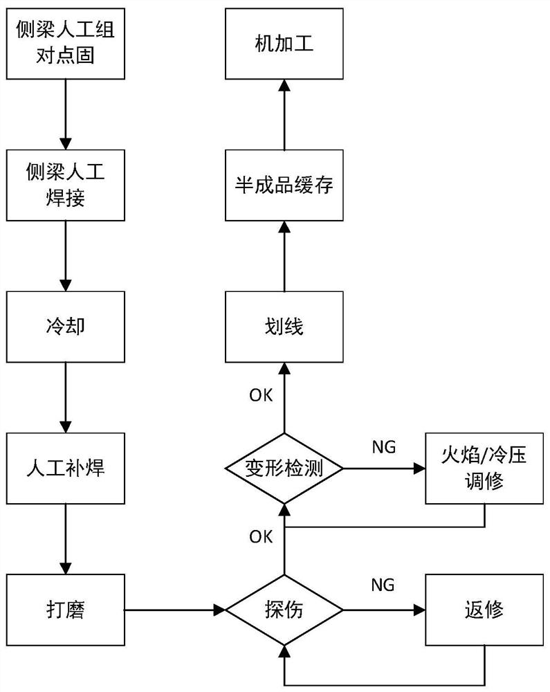
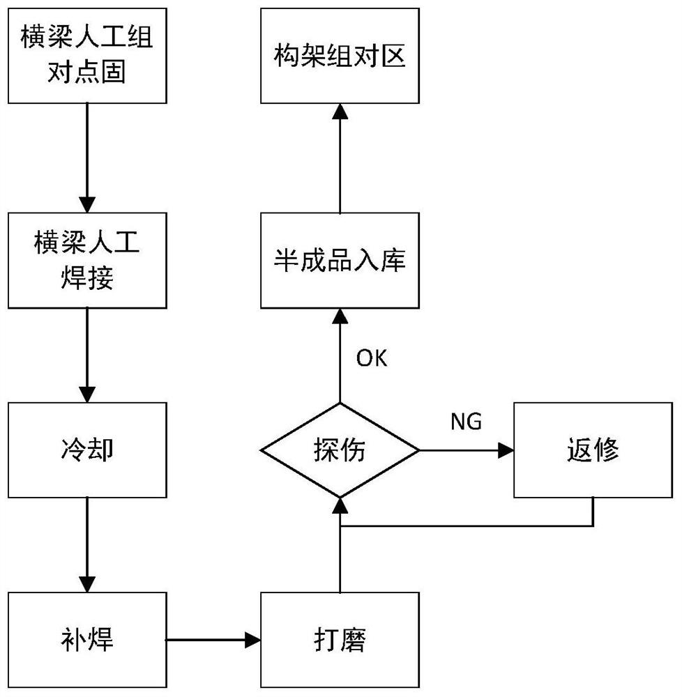
[0038] combined with Figure 8 to attach Figure 15 , a rail transit box girder frame welding process, which includes three sub-processes of side beam welding process, beam welding process and frame welding process; wherein there is no time sequence between the side beam welding process and the beam welding process, and the side beam welding process and the beam welding process are completed After the beam welding process, the frame welding process is carried out;

[0039] The welding process of the side beam includes the following steps: manual assembly of the inner cavity → automatic welding of the inner cavity → cooling → point fixing of the brake hanger and the inner cavity → automatic welding of the brake hanger and the inner cavity → cooling →Repair welding of inner cavity→Manual assembly and point fixing of upper cover→Priming of outer weld seam→Auto...


PUM


Abstract

The invention discloses a rail transit box girder framework welding process and a lean production layout method thereof. The process specifically comprises three sub-processes of a side beam welding process, a cross beam welding process and a framework welding process, wherein no time sequence exists between the side beam welding process and the cross beam welding process; after the side beam welding process and the cross beam welding process are completed, the framework welding process is carried out, a mode of combining manual tack welding and mechanical welding is adopted in the welding process, and one-time straightening adjustment and repair are carried out after a side beam outer weld joint is welded and before a small accessory is tack-welded, so that the deformation after welding is controlled, and the welding efficiency and quality can be improved. According to the lean production layout method, three core parts including the automatic welding area, the manual assembly area and the double-stacking-machine-contained three-dimensional warehouse are subjected to automatic welding area centering or three-dimensional warehouse centering main body arrangement and then matched with the peripheral process area, so that the production efficiency can be greatly improved.

Description

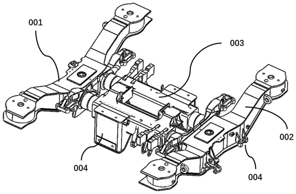
technical field [0001] The invention relates to the technical field of manufacturing welding processes and corresponding production process layout methods, in particular to a welding process of a box girder frame in the rail transit industry and its corresponding lean production layout method. Background technique [0002] Box girder frame is an important load-bearing structure of rail transit vehicles, and its welding quality is directly related to the reliability and safety of vehicles. combined with figure 1 , the rail transit vehicle box girder frame in the prior art is composed of the left side beam assembly 001, the right side beam assembly 002 and the cross beam assembly 003. Each of the three major components includes multiple welding processes. Welding together, the traditional welding process is all manual welding, but with the rapid progress of the current intelligent manufacturing technology, the rail transit industry is gradually advancing and applying. Among ...

Claims


Application Information

Patent Timeline
IPC IPC(8): B23P23/00B23K31/02
CPCB23P23/00B23K31/02
Inventor 隋阳江书平高升程立伟
Owner 武汉中车电牵科技有限公司
Learn More