Wiring device

A technology of wiring device and sealing device, applied in the direction of connection, conductive connection, electrical component connection, etc., can solve the problems of leakage, copper oxidation and corrosion, heat generation, etc., and achieve the effect of safe and reliable wiring and long-term stable operation.

Pending Publication Date: 2020-11-20
无锡畅欧光电科技有限公司
View PDF0 Cites 0 Cited by
  • Summary
  • Abstract
  • Description
  • Claims
  • Application Information

AI Technical Summary

Problems solved by technology

From the perspective of the factory, the factory needs to inject the power cord and the plastic parts first, and then assemble the product, which will bring inconvenience to the assembly and the production steps will be cumbersome.
Therefore, many manufacturers do not install a fixed wiring device on the product power cord, but provide a separate wiring device, which requires a power cord of more than ten centimeters to be drawn from the wiring device for interconnection with the lead-out wire of the product, which is not only inconvenient The use of the customer also increases the instability of the circuit system; from the customer's point of view, this product has no protective performance, and the copper sheet will be oxidized and corroded after a long time, and there will be local heating or even leakage when it encounters rainwater or other impurities. risk

Method used


Image

  • Wiring device
  • Wiring device
  • Wiring device

Examples


Embodiment Construction

[0037] The present invention will be further described in detail below in conjunction with the accompanying drawings and embodiments. It should be understood that the specific embodiments described here are only used to explain the present invention, but not to limit the present invention. In addition, it should be noted that, for the convenience of description, only some structures related to the present invention are shown in the drawings but not all structures.

[0038] In the description of the present invention, unless otherwise clearly specified and limited, the terms "connected", "connected" and "fixed" should be understood in a broad sense, for example, it can be a fixed connection, a detachable connection, or an integrated ; It can be a mechanical connection or an electrical connection; it can be a direct connection or an indirect connection through an intermediary, and it can be the internal communication of two components or the interaction relationship between two ...


PUM


Abstract

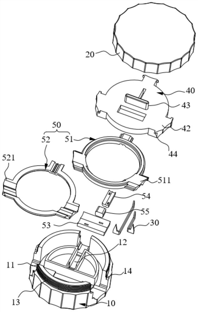
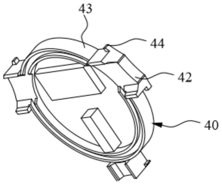
The invention belongs to the technical field of line connectors, and particularly relates to a wiring device, which comprises a first cover body, a second cover body, a spinning plate, a sealing device and a conductive metal sheet, and is characterized in that the side surface of the first cover body is provided with a plurality of wire holes, and the conductive metal sheet is fixed in the first cover body and is provided with two spine ends; the spinning plate is located between the second cover body and the first cover body, and a protruding block is arranged on the lower side of the spinning plate. The sealing device is used for sealing the space between the spinning plate and the first cover body. During use, a wire is located above the conductive metal sheet, the second cover body isrotated to press the spinning plate to extrude the wire, the spine ends are promoted to pierce a sheath insulating layer of the wire, the two spine ends are in contact with inner cores of a main lineand a branch line respectively, and circuit conduction is achieved. In the wiring process, the power line does not need to be peeled or cut off, auxiliary tools are not used, and operation is simple and rapid; in addition, the built-in sealing device effectively isolates rainwater or other impurities, so that wiring is safer and more reliable, and the device is suitable for severe working environments such as damp, dust, outdoor rain and snow weather and the like.

Description

technical field [0001] The invention relates to the technical field of line connectors, in particular to a wiring device. Background technique [0002] The use of electrical equipment often requires the connection of wires. At present, most of the quick wiring devices for safety voltage on the market are inconvenient to use and have no waterproof function, so they are not suitable for harsh outdoor conditions caused by wind and rain. At present, the common quick wiring device is usually to press the end of the power cord into a plastic part with a special tool (or fix the power cord in the plastic part by injection molding), and there is a sharp copper wire at one end of the plastic part. The piece is connected to the wire, and the sharp end is exposed outside the plastic part. During use, the exposed copper spikes pierce the insulation layer of the power cord and connect the internal wires through threads or buckles, so as to achieve the connection between the main line an...

Claims


Application Information

Patent Timeline
Patent Type & Authority Applications(China)
IPC IPC(8): H01R11/01H01R11/09H01R4/2406H01R4/2408
CPCH01R4/2408H01R11/01H01R11/09H01R4/2406
Inventor 金钊张强
Owner 无锡畅欧光电科技有限公司
Why Eureka
Try Eureka