
Missile body analyzing and positioning method based on double/multi-base radar

A positioning method and radar position technology, applied in the field of radar, can solve the problems of large positioning error, inability to apply bistatic synthetic aperture radar, failure of adjacent pixel iteration method, etc., and achieve the effect of wide application range

Active Publication Date: 2020-11-20
XIDIAN UNIV
View PDF11 Cites 2 Cited by
  • Summary
  • Abstract
  • Description
  • Claims
  • Application Information

AI Technical Summary

Problems solved by technology

It is used to solve the problem in the prior art that due to ignoring the Doppler space-varying characteristics of bistatic SAR, it is only applicable to the shift-invariant mode of bistatic SAR and cannot be applied to any configuration of bistatic SAR
At the same time, it can also be used to solve the problem that the adjacent pixel iterative method used in the prior art to obtain other target position information has very strict requirements for the selection of initial parameters, the initial parameter selection is not accurate, and the adjacent pixel iterative method will fail.
Moreover, it can also solve the problem that in the prior art, in the terminal guidance stage of the missile, the error of the inertial navigation data of the beam pointing angle of the transceiver platform will increase with the increase of time, causing the subsequent positioning error to be too large and unable to meet the precise guidance requirements of the missile terminal guidance stage. The problem

Method used


Image

  • Missile body analyzing and positioning method based on double/multi-base radar
  • Missile body analyzing and positioning method based on double/multi-base radar
  • Missile body analyzing and positioning method based on double/multi-base radar

Examples


Embodiment Construction

[0045] The present invention will be further described in detail below in conjunction with the accompanying drawings and specific embodiments.

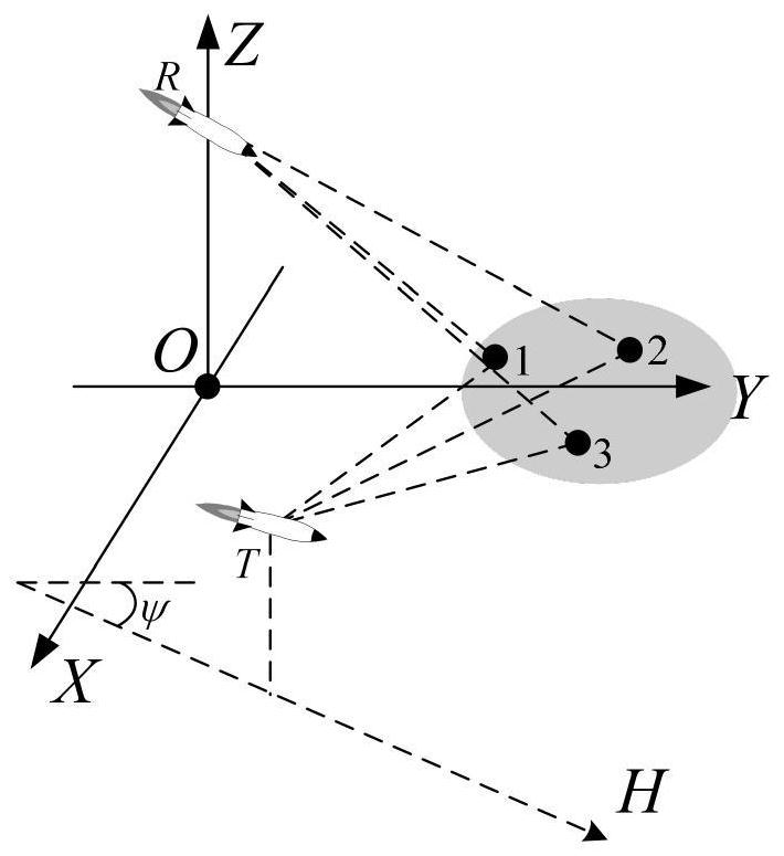
[0046] In the embodiment of the present invention, the missile-borne bistatic synthetic aperture radar (SAR) in the missile-borne dual / multistatic radar is taken as an example, and the positioning principle of the missile-borne dual / multistatic radar is the same as that of the missile-borne bistatic SAR.

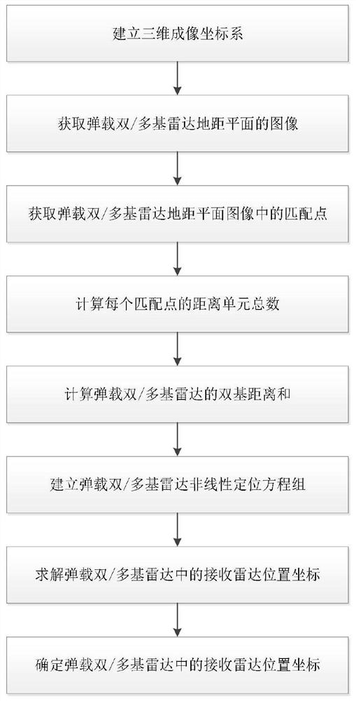
[0047] refer to figure 1 , the implementation steps of the present invention are further described in detail.

[0048] Step 1, establish a three-dimensional imaging coordinate system.

[0049] When the three-dimensional imaging coordinate system is established, the sub-satellite point of the receiving radar in the missile-borne bistatic SAR is used as the coordinate origin, the flight direction of the receiving radar is used as the positive direction of the Y axis, and the vertical upward direction perpendicular to the ground is us...


PUM


Abstract

The invention discloses a missile body analysis and positioning method based on a double / multi-base radar. The implementation scheme comprises the following specific steps: 1) establishing a three-dimensional imaging coordinate system; 2) acquiring an image of a missile-borne double / multi-base radar ground distance plane; 3) obtaining matching points in the missile-borne double / multi-base radar ground distance plane image; 4) calculating the total number of distance units of each matching point; 5) calculating the bistatic distance sum of the missile-borne bistatic / multistatic radar; 6) establishing a missile-borne double / multi-base radar nonlinear positioning equation set; 7) solving the position coordinates of the receiving radar in the missile-borne dual / multi-base radar; and 8) determine the position coordinates of the receiving radar in the missile-borne dual / multi-base radar. The missile-borne double / multi-base radar positioning method is used for positioning the receiving radarin the missile-borne double / multi-base radar in the missile terminal guidance stage, and has the advantages of being high in positioning precision, wide in application range and good in robustness.

Description

technical field [0001] The invention belongs to the field of radar technology, and further relates to a dual / multi-base radar projectile analysis and positioning method in the field of radar signal processing technology. The invention can be used to realize the precise positioning of the receiving radar seeker when striking the dual / multi-base radar target. Background technique [0002] The missile-borne dual / multi-base radar can realize two-dimensional high-resolution imaging of the target area directly in front of the receiving radar, breaking the defect that the missile-borne single-base radar cannot look forward to imaging, and expanding the application of the radar imaging system in the terminal guidance stage. Dual / multi-base radar guidance technology has been widely used in the field of positioning. [0003] Xu Yushi proposed a bistatic radar target positioning method based on the range-Doppler equation in his paper "Bistatic (Multistatic) Synthetic Aperture Radar Po...

Claims


Application Information

Patent Timeline
IPC IPC(8): G01S13/88G01S13/90G01S13/89G01S13/00G01S13/42
CPCG01S13/883G01S13/9021G01S13/9043G01S13/895G01S13/9058G01S13/003G01S13/42Y02A90/10
Inventor 李亚超詹珩艺宋炫武春风吕金虎全英汇
Owner XIDIAN UNIV
Learn More