
Precise guide rail for CNC machine tool

A technology for precision guide rails and CNC machine tools, applied in the field of precision guide rails, can solve the problems of friction consumption of sliders and rails, affecting normal use, and low practicability, and achieve the effects of reducing use loss, improving practicability, and improving durability.

Active Publication Date: 2020-11-20
平湖市成功机械有限公司
View PDF7 Cites 0 Cited by
  • Summary
  • Abstract
  • Description
  • Claims
  • Application Information

AI Technical Summary

Problems solved by technology

[0007] In order to solve the above technical problems, the present invention provides a precision guide rail for CNC machine tools to solve the problem that when the existing precision guide rail is in use, there is a large friction force between the slider and the track, which may easily cause friction between the slider and the track. Friction consumption leads to a decrease in subsequent accuracy and affects normal use, and the height of the slider and the track cannot be adjusted after the installation is completed, which cannot adapt to different working environments, poor adaptability, and low practicability.

Method used


Image

  • Precise guide rail for CNC machine tool
  • Precise guide rail for CNC machine tool
  • Precise guide rail for CNC machine tool

Examples


Embodiment

[0035] as attached figure 1 to attach Figure 8 Shown:

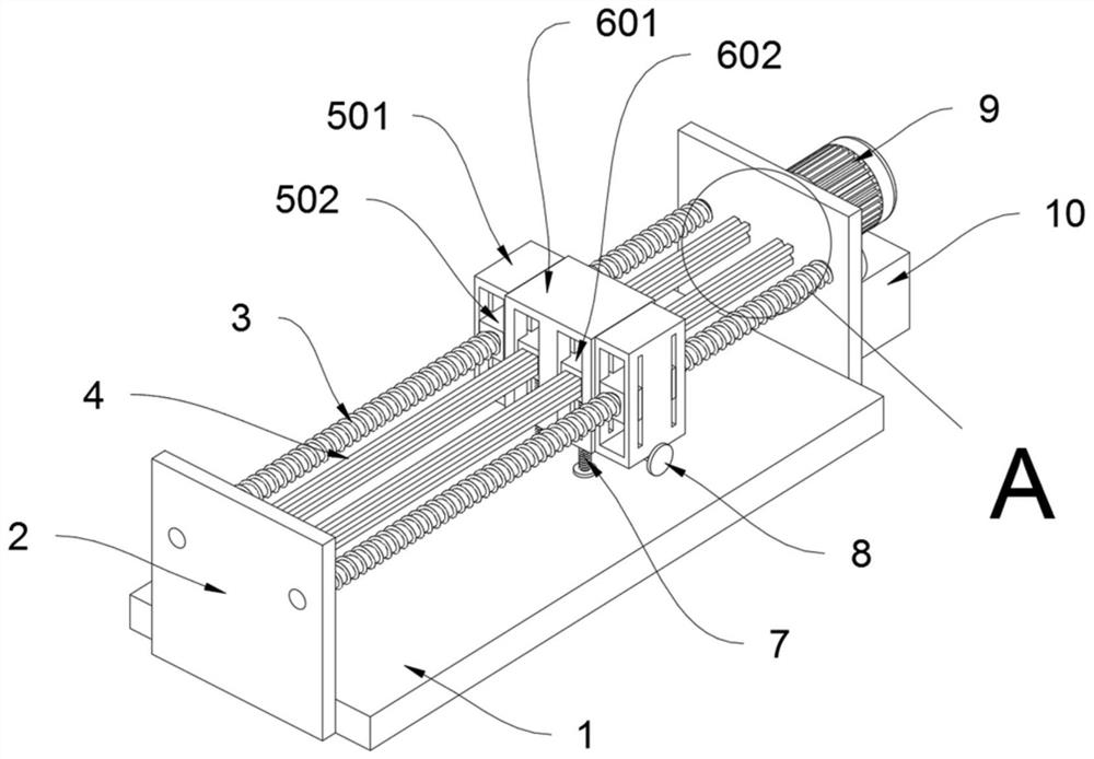
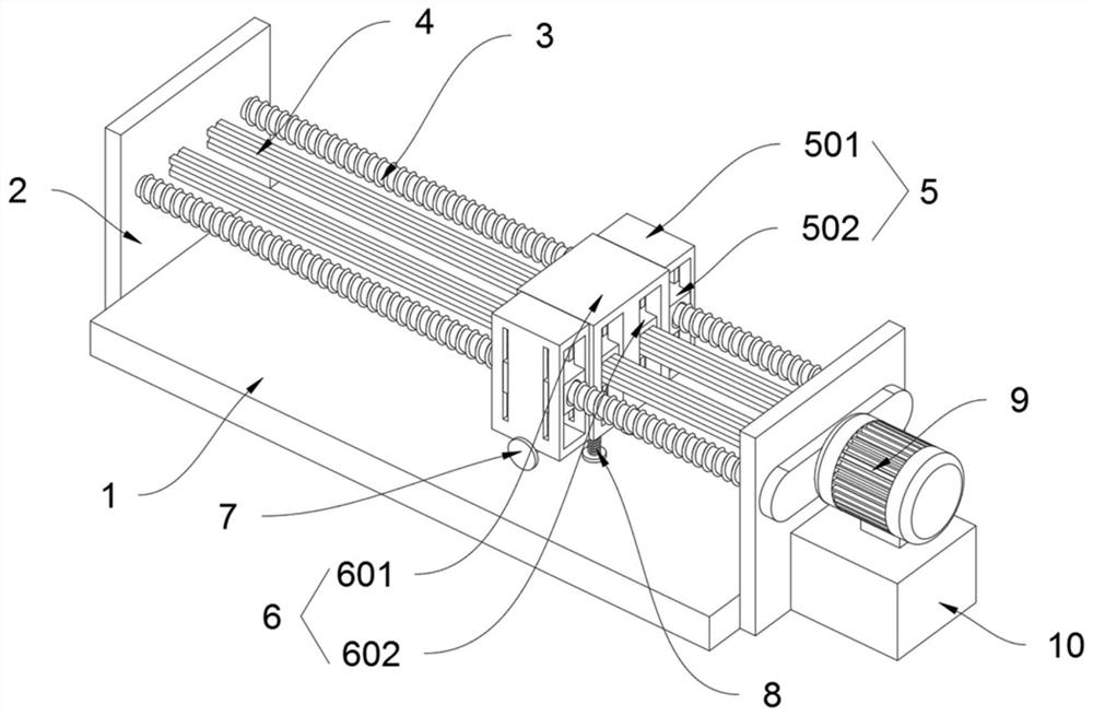
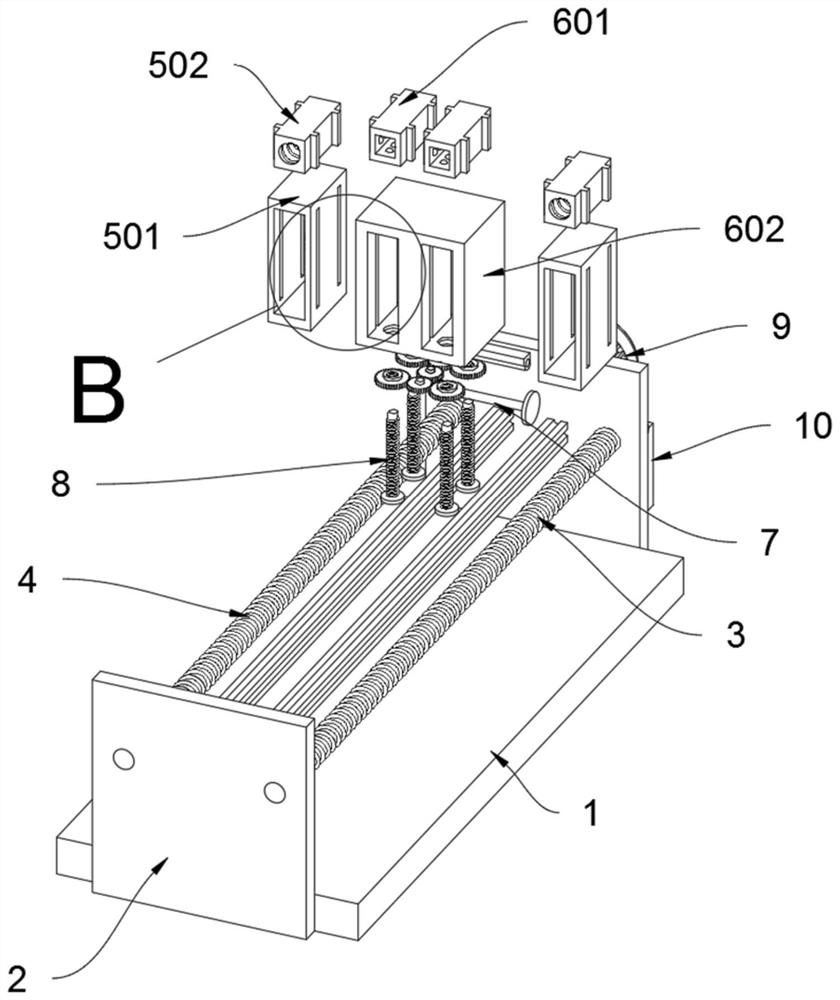
[0036] The present invention provides a precision guide rail for CNC machine tools, comprising a guide rail platform 1, a drive shaft 3, a guide rail column 4, a drive mechanism 5, a guide rail mechanism 6, an adjustment mechanism 7, a positioning rod 8 and a drive motor 9; the guide rail platform 1 Both sides of the drive shaft 3 are fixedly connected to the support plate 2; the two ends of the drive shaft 3 are rotatably connected to the inside of the support plates 2 on both sides of the guide rail platform 1; the two ends of the guide rail column 4 are fixedly connected to the inside of the support plates 2 on both sides of the guide rail platform 1, And the rail post 4 is located inside the drive shaft 3; the drive mechanism 5 is made up of a drive sleeve 501 and a drive block 502; the drive block 502 is plugged in the drive sleeve 501, and the drive shaft 3 is plugged in the drive block 502; The shaft body of the...


PUM


Abstract

The invention discloses a precise guide rail for a CNC machine tool, and relates to the technical field of precise guide rails. The precise guide rail solves the problems that the height of a slidingblock and a rail of an existing precise guide rail cannot be adjusted after installation, the existing precise guide rail cannot adapt to different working environments, and the adaptability is poor.The precise guide rail for the CNC machine tool comprises an adjusting mechanism; and the adjusting mechanism is composed of an adjusting rod, a composite transmission wheel, a driven gear and a positioning gear. According to the precise guide rail for the CNC machine tool, the use height of a guide rail shell can be adjusted through the adjusting mechanism, when the adjusting rod is rotated, theadjusting rod drives the composite transmission wheel to rotate through a bevel gear, the composite transmission wheel drives the positioning gear to rotate through the driven gear, when the positioning gear rotates, the positioning rod can be driven to ascend and descend through a positioning rotating block under the action of threads of a rod body of the positioning rod, so that the guide rail shell ascends or descends, then the use height of the device is changed, the adaptability is high, and the practicability of the device is improved.

Description

technical field [0001] The invention belongs to the technical field of precision guide rails, and more specifically relates to a precision guide rail for CNC machine tools. Background technique [0002] A precision rail is a groove or ridge made of metal or other materials that can bear, fix, and guide a device for moving devices or equipment. Longitudinal grooves or ridges on the surface of rails for guiding and fixing machine parts, special equipment, instruments, etc. [0003] Precision guide rails, also known as slide rails, linear guide rails, and linear slide rails, are used in linear reciprocating motion applications. They have a higher rated load than linear bearings, and can bear a certain torque at the same time. They can achieve high-precision linear motion under high load conditions. sports. [0004] For example, in the patent with the application number: CN201710187911.3, a decoupling identification method for the straightness error of the base surface of the ...

Claims


Application Information

Patent Timeline
Patent Type & Authority Applications(China)
IPC IPC(8): B23Q1/01
CPCB23Q1/017
Inventor 游旭
Owner 平湖市成功机械有限公司
Learn More