Actuating mechanism of library robot
A technology of actuators and robots, applied in manipulators, manufacturing tools, etc., can solve the problems of large fingers, increased difficulty in control, and poor integrity, and achieve diverse and flexible handling methods, flexible and stable operations, and control bit-wise accurate effects
- Summary
- Abstract
- Description
- Claims
- Application Information
AI Technical Summary
Problems solved by technology
Method used
Image
Examples
specific Embodiment approach 1
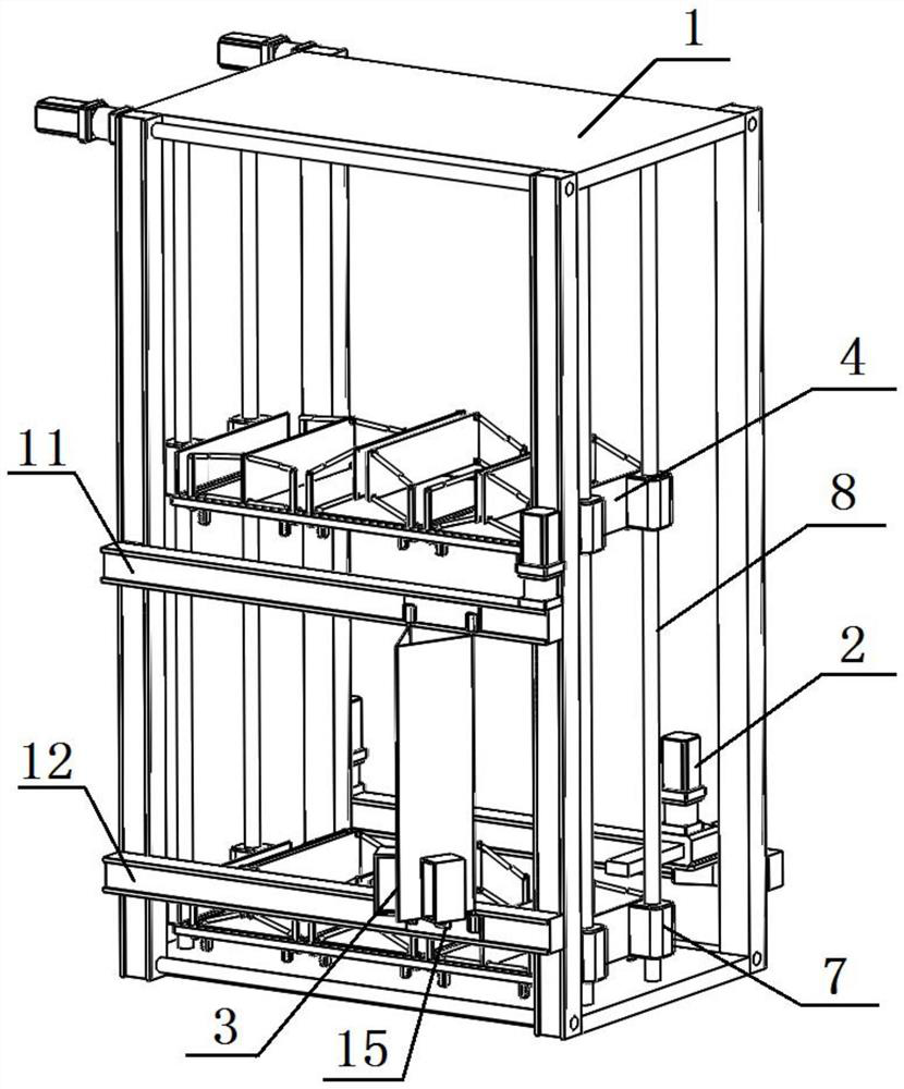
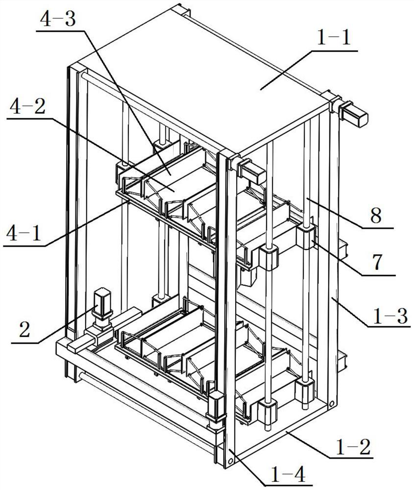
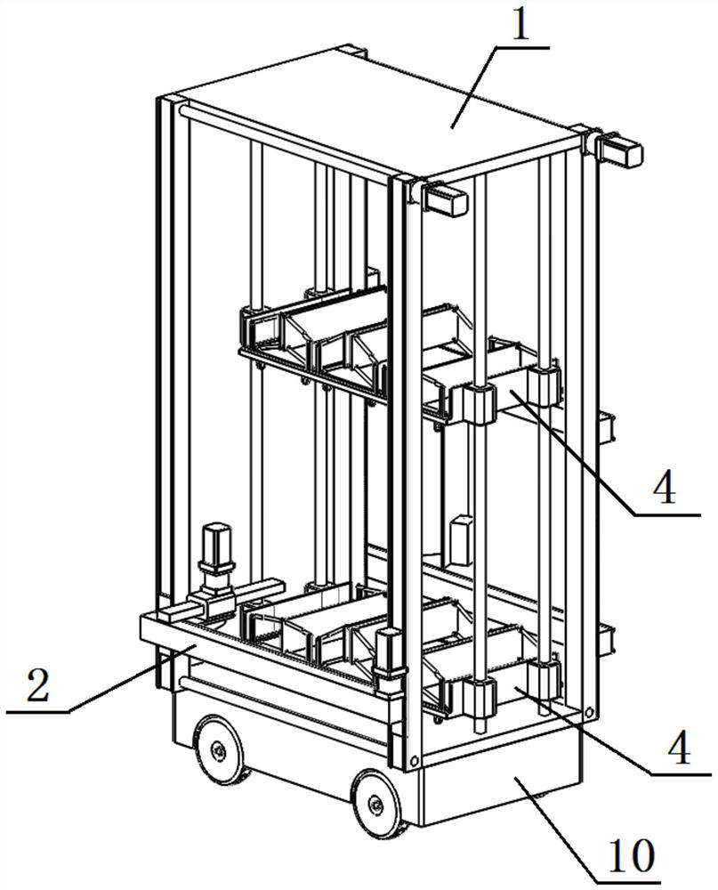
[0037] Specific implementation mode one: as figure 1 , figure 2 , image 3 , Figure 4 , Figure 5 , Figure 6 , Figure 7 , Figure 8 , Figure 9 , Figure 10 , Figure 11 , Figure 12 , Figure 13 , Figure 14 , Figure 15 , Figure 16 , Figure 17 and Figure 18 As shown, this specific embodiment adopts the following technical solutions: this embodiment includes a total support frame 1, a push assembly 2, a position control clip 3 and at least one mobile bookshelf 4;
[0038] The total support frame 1 is vertically arranged, at least one mobile bookshelf 4 is arranged in the total support frame 1, and target books 5 are arranged in the mobile bookshelf 4, and the mobile bookshelf 4 reciprocates along the height direction of the total support frame 1, and the position control clip 3 and the push assembly 2 are both arranged on the overall support frame 1, the push assembly 2 reciprocates along the height direction and / or the length direction of the overall s...
specific Embodiment approach 2
[0040]Embodiment 2: This embodiment is a further limitation of Embodiment 1. The mobile bookshelf 4 includes a supporting plate 4-1, N bottom plates 4-2, 2N splints 4-3, and 4N first swing rods 4-5. , 4N second swing bars 4-6 and 4N vertical bars 4-8, the supporting plate 4-1 is horizontally arranged in the overall support frame 1, and 4N vertical bars 4-8 are vertically arranged side by side on the supporting plate 4-1 N bottom plates 4-2 are arranged side by side on the supporting plate 4-1, two splints 4-3 are vertically arranged on both sides of each bottom plate 4-2, and each end of the bottom of the bottom plate 4-2 A rack 4-4 is provided at the corner, and the opposite sides of the two splints 4-3 on the same bottom plate 4-2 are clamping surfaces, and a clamping surface for matching the target book 5 is formed between the two clamping surfaces. Gap 4-9, two first swing rods 4-5 are arranged side by side at the bottom of the outer side of each splint 4-3, each first swi...
specific Embodiment approach 3
[0050] Specific Embodiment 3: This embodiment is a further limitation of Embodiment 1 or 2. The supporting plate 4-1 includes a horizontal plate 4-1-1 and two vertical plates 4-1-2. The horizontal plate 4-1-1 Set horizontally, the horizontal plate 4-1-1 is a rectangular plate body, two vertical plates 4-1-2 are vertically arranged side by side at the two ends of the horizontal plate 4-1-1, and the horizontal plate 4-1-1 is arranged along its plate The thickness direction processing has a plurality of placement holes 6 for engagement.
[0051] In the present embodiment, the meshing placement hole 6 is used to place the rack 4-4 and the gear 4-7 that cooperate with each other. Each rack 4-4 and its corresponding gear 4-7 form a group of meshing structures. 6 includes a plurality of first placement holes 6-1 and four second placement holes 6-2, the four second placement holes 6-2 are respectively arranged at the four end corners of the horizontal plate 4-1-1, each A rack 4-4 and...
PUM
 Abstract
Description
Claims
Application Information
 - R&D
- Intellectual Property
- Life Sciences
- Materials
- Tech Scout
- Unparalleled Data Quality
- Higher Quality Content
- 60% Fewer Hallucinations
Browse by: Latest US Patents, China's latest patents, Technical Efficacy Thesaurus, Application Domain, Technology Topic, Popular Technical Reports.
© 2025 PatSnap. All rights reserved.Legal|Privacy policy|Modern Slavery Act Transparency Statement|Sitemap|About US| Contact US: help@patsnap.com


