Water squeezing mechanism
A technology of squeezing rollers and squeezing parts, which is applied to cleaning machinery, carpet cleaning, floor cleaning, etc., and can solve problems such as unsmoothness, physical exertion, and inability to squeeze water out
- Summary
- Abstract
- Description
- Claims
- Application Information
AI Technical Summary
Problems solved by technology
Method used
Image

Examples
Embodiment 1
[0079] according to Figure 2 to Figure 4 , Figures 12 to 14 As shown, the water squeezing mechanism described in this embodiment is mainly suitable for squeezing and dehydrating the mop equipped with wipes.
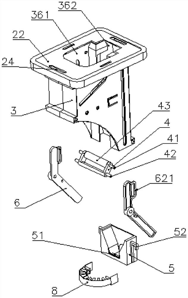
[0080] From the structural point of view, the water squeezing mechanism generally includes a mounting seat 3, and the mounting seat 3 is movably installed with a squeezing part 4, a driving part 5 and a linkage part 6. It includes two relatively stable states, namely the first state in which the extruding part 4 and the abutting surface 35 on the mounting seat 3 are far away from each other, and the state in which the extruding part 4 and the abutting surface 35 on the mounting seat 3 are close to each other In the second state, in the second state, the extruding part 4 can extrude and dehydrate the wipe 13 placed in the perforation 36 .
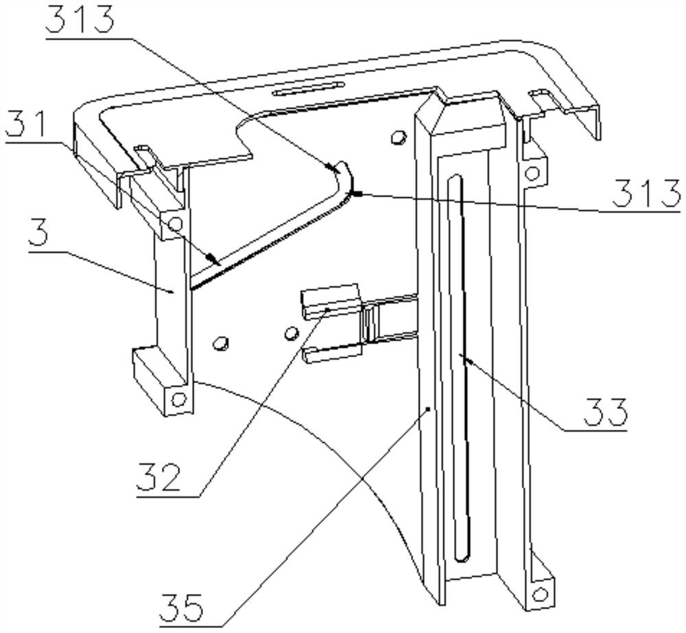
[0081]The mounting base 3 is suitable for installing various linkage components or mechanisms. Usually, the mounting base 3 can be...
Embodiment 2
[0108] The difference between this embodiment and Embodiment 1 is that this embodiment shows a cleaning tool with the above-mentioned water squeezing mechanism.
[0109] The cleaning tool includes a mop, and the mop is provided with the above-mentioned water squeezing mechanism.
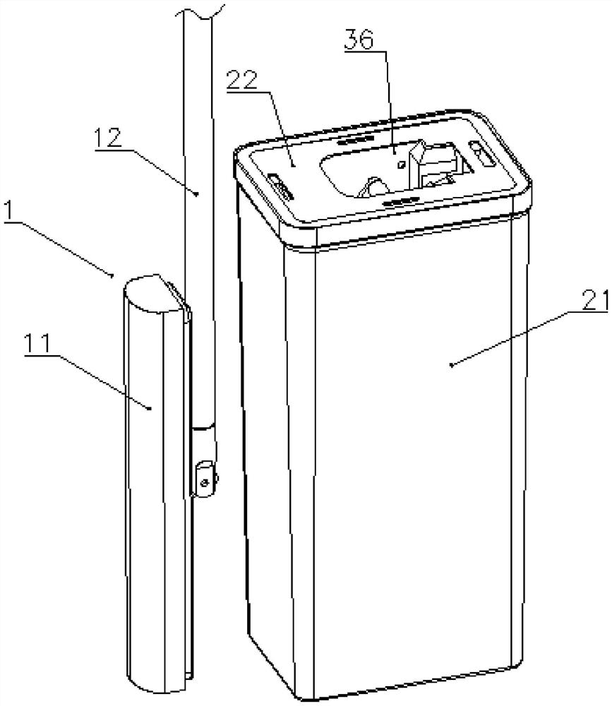
[0110] The mop 1 comprises a mop rod 12, a mop head 11 movably connected to the lower end of the mop rod, the mop head is provided with a wiper 13, and the mop head is provided with a drive end 14 which cooperates with the drive part.
[0111] When cleaning, the mop head rotates to the cleaning state parallel or substantially parallel to the mop rod, and the mop head can be inserted into the opening without hindrance; when squeezing water, the mop head rotates to the state of squeezing water parallel or substantially parallel to the mop rod, and Make the driving end contact the driving part, push the driving part, and then drive the extruding part to move to the second state. When the mop head is pul...
Embodiment 3
[0113] The difference between this embodiment and other embodiments lies in the addition of a restoring force adjustment structure.
[0114] In order to adapt to the extrusion dehydration effect of mops of different thicknesses, an adjustment structure suitable for adjusting the size of the restoring force can also be provided. The adjustment structure includes a hook 37 for fixing the spring, and a plurality of side-by-side hanging holes 64 for fixing the spring. By adjusting the fixed position of the spring and the direction of expansion and contraction, the size of the restoring force can be adjusted to adapt to wipes of different thicknesses. .
[0115] In some other embodiments, the adjustment structure can also adopt other forms, such as providing several optional fixed positions of the reset member, so as to facilitate the adjustment of the length or angle of the elastic arm of the spring or torsion spring, thereby adjusting the spring restoring force the size of.
PUM
 Abstract
Description
Claims
Application Information
 - R&D
- Intellectual Property
- Life Sciences
- Materials
- Tech Scout
- Unparalleled Data Quality
- Higher Quality Content
- 60% Fewer Hallucinations
Browse by: Latest US Patents, China's latest patents, Technical Efficacy Thesaurus, Application Domain, Technology Topic, Popular Technical Reports.
© 2025 PatSnap. All rights reserved.Legal|Privacy policy|Modern Slavery Act Transparency Statement|Sitemap|About US| Contact US: help@patsnap.com