Eureka AIR delivers breakthrough ideas for toughest innovation challenges, trusted by R&D personnel around the world.
an air humidifier
What is Al technical title?
Al technical title is built by PatSnap Al team. It summarizes the technical point description of the patent document.
An air humidifier and humidification device technology, which is applied to the air humidification system, air treatment details, heating methods, etc., can solve the problems of inconvenient disassembly, disinfection and cleaning of the humidifier, easy breeding of bacteria in the air jet, and contamination of the humidified space, and achieves the eruption range. Comprehensive, easy and precise control, simplified disassembly effect
Active Publication Date: 2021-01-12
SHENZHEN JISU TECHNOLOGV CO LTD
View PDF7 Cites 0 Cited by
Summary
Abstract
Description
Claims
Application Information
AI Technical Summary
This helps you quickly interpret patents by identifying the three key elements:
Problems solved by technology
Method used
Benefits of technology
Problems solved by technology
[0003] There are many types of air humidifiers today, but each humidifier has certain advantages and inevitably has some disadvantages and common problems in use. The most important thing is that the spraying part of the device will easily breed bacteria when used for a long time , thus causing pollution to the humidification space, long-term use may easily cause physical discomfort, but the outlet end of these humidifiers is often not easy to disassemble for disinfection and cleaning, and in order to ensure the uniformity and efficiency of humidification, some humidifiers on the market now use louvers There is still a lot of room for improvement in the uniformity of humidification
Method used
Image
Click on the blue label to locate the original text in one second.
Reading with bidirectional positioning of images and text.
Examples
Embodiment Construction
[0031] The present invention will be further described below in conjunction with the accompanying drawings and embodiments.
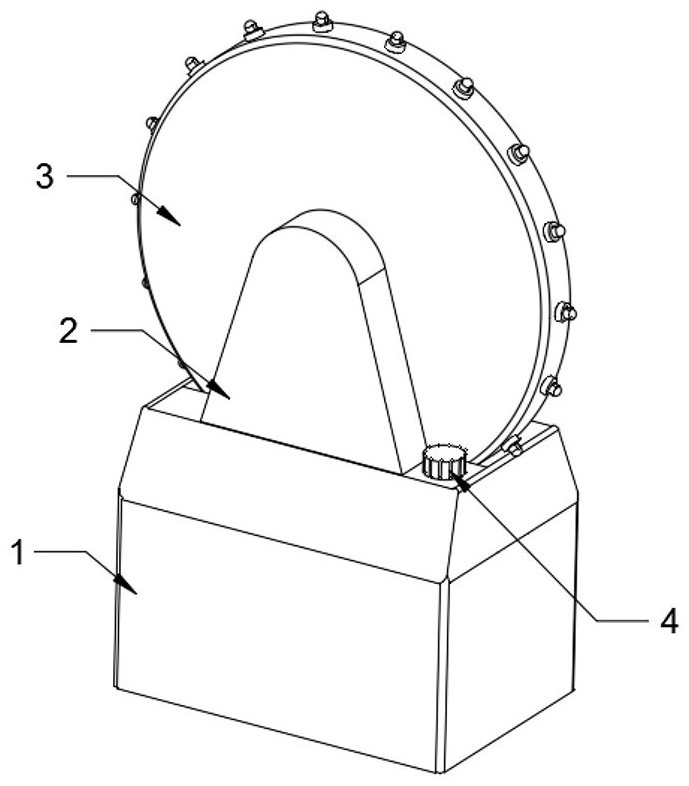
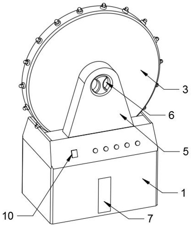
[0032] Please refer to figure 1 , figure 2 , image 3 , Figure 4 , Figure 5 , Figure 6 , Figure 7 , Figure 8 , Figure 9 , Figure 10 , Figure 11 , Figure 12 , Figure 13 and Figure 14 ,in, figure 1 One of the overall structural schematic diagrams provided by the present invention; figure 2 The second schematic diagram of the overall structure provided for the present invention; image 3 Schematic diagram of the structure of the humidifying device provided by the present invention; Figure 4 Schematic diagram of the arc groove structure provided by the present invention; Figure 5 Schematic diagram of the structure of the driver and connector provided for the present invention; Figure 6 Schematic diagram of the cooperating structure of the shaft cylinder and the shaft cylinder provided by the present invention; Figure 7 Sch...
PUM
Abstract
The invention provides an air humidifier. The air humidifier comprises a humidifying device, a left supporting table, a right supporting table and a control element, the humidifying device comprises abase shell, an arc-shaped groove is formed in the top face of the base shell, the left supporting table and the right supporting table are fixedly arranged on the positions, located on the two sidesof the arc-shaped groove, of the top face of the base shell respectively, the control element is installed on one side, close to the right supporting table, of the base shell, an annular multi-stationwet spraying device capable of controlling and blocking air spraying is arranged at position, between the left supporting table and the right supporting table, of the top of the base shell. Accordingto the air humidifier, the moisture spraying stations are uniform, moisture can be emitted more rapidly through rotation, the spraying range is comprehensive, the humidification of the surrounding environment is effectively improved, the humidification uniformity is good, and therefore accurate control over air humidity can be achieved conveniently; and meanwhile, compared with traditional fixedinstallation of an air outlet part, the disinfection treatment difficulty is simplified through convenient disassembly of the wet spraying device, resistance caused by later disinfection is reduced, maintenance by a user is facilitated, and the use safety is improved.
Description
technical field [0001] The invention relates to the technical field of air humidifiers, in particular to an air humidifier. Background technique [0002] A humidifier is a household appliance that increases the humidity of a room. The humidifier can humidify a designated room. With the current use of air conditioners, the air in the room is relatively dry. The use of a humidifier can effectively balance the problem of dry air. [0003] There are many types of air humidifiers today, but each humidifier has certain advantages and inevitably has some disadvantages and common problems in use. The most important thing is that the spraying part of the device will easily breed bacteria when used for a long time , thus causing pollution to the humidification space, long-term use may easily cause physical discomfort, but the outlet end of these humidifiers is often not easy to disassemble for disinfection and cleaning, and in order to ensure the uniformity and efficiency of humidific...
Claims
Application Information
Patent Timeline
Application Date:The date an application was filed.
Publication Date:The date a patent or application was officially published.
First Publication Date:The earliest publication date of a patent with the same application number.
Issue Date:Publication date of the patent grant document.
PCT Entry Date:The Entry date of PCT National Phase.
Estimated Expiry Date:The statutory expiry date of a patent right according to the Patent Law, and it is the longest term of protection that the patent right can achieve without the termination of the patent right due to other reasons(Term extension factor has been taken into account ).
Invalid Date:Actual expiry date is based on effective date or publication date of legal transaction data of invalid patent.