Workpiece Fixtures for Vertical Machining Centers
A fixed device, vertical technology, used in positioning devices, metal processing mechanical parts, metal processing and other directions, can solve the problem of unable to reduce the buffer of the device, unable to lock and so on, to eliminate the damage of the device, ensure the fixation, and avoid manual operation. Effect
- Summary
- Abstract
- Description
- Claims
- Application Information
AI Technical Summary
Problems solved by technology
Method used
Image
Examples
Embodiment 1
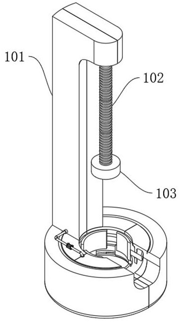
[0030] refer to Figure 1-6 , a workpiece fixing device for a vertical machining center, comprising: a vertical machining frame 101, an elastic hydraulic tube 102 and an adsorption probe 103, the upper end of the vertical machining frame 101 is fixedly connected to the upper end of the elastic hydraulic tube 102, and the lower end of the elastic hydraulic tube 102 is connected to the upper end of the elastic hydraulic tube 102 The axis of the upper surface of the adsorption probe 103 is fixedly connected;
[0031] The vertical processing frame 101 is provided with a starting chamber 104, a locking inflatable chamber 105 and a mobile fixed chamber 106 in sequence from top to bottom. The upper end of the starting chamber 104 is fixedly installed with a driving mechanism, and the inner part of the starting chamber 104 is equipped with a pneumatic buffer fixing mechanism. Locking inflatable chamber 105 is equipped with locking inflatable mechanism, and mobile fixed chamber 106 is ...
Embodiment 2
[0033] Embodiment 2: the difference based on Embodiment 1 is;
[0034] The drive mechanism includes: a rotating gear 201, a rotating wheel 202, a rotating wheel set 203, a servo motor 204 and a rotating screw mandrel 205, and the main shaft of the servo motor 204 is sequentially connected with the rotating screw mandrel 205, a group of rotating wheel sets 203, from top to bottom. The rotating wheel 202, another group of rotating wheel sets 203 are fixedly connected with the rotating gear 201, the rotating screw mandrel 205 is threadedly connected with the pneumatic buffer fixing mechanism, the rotating gear 201 is meshed with the mobile fixing mechanism, and the rotating wheel 202 is flexibly connected with the locking inflation mechanism. The rotating wheel set 203 is fixedly connected with the locking inflation mechanism;
[0035]The mobile fixing mechanism includes: a rotating gear ring 301 and a moving block 302. The rotating gear ring 201 is meshed with the rotating gear ...
Embodiment 3
[0041] Embodiment 3: based on Embodiment 1 and 2, but different again is;
[0042] The pneumatic buffering and fixing mechanism includes: compression moving block 601, compression air bag 602, Unicom hose 603 and regulating valve 604, the compression moving block 601 is movably socketed on the rotating screw rod 205, the lower surface of the other side of the compression moving block 601 and the compression air bag The upper end of 602 is fixedly connected, the lower end of the compressed airbag 602 is fixedly connected with the inner wall of the starting chamber 104, the lower end of the compressed airbag 602 is fixedly connected with the upper surface of the rotating ring 401 through the connecting hose 603, the inside of the rotating ring 401 is in a hollow state, and the connecting hose 603 is fixed A regulating valve 604 is installed.
[0043] During use, the rotating wheel 202 and the rotating screw mandrel 205 are driven to rotate synchronously by starting the servo mot...
PUM
 Abstract
Description
Claims
Application Information
 - R&D
- Intellectual Property
- Life Sciences
- Materials
- Tech Scout
- Unparalleled Data Quality
- Higher Quality Content
- 60% Fewer Hallucinations
Browse by: Latest US Patents, China's latest patents, Technical Efficacy Thesaurus, Application Domain, Technology Topic, Popular Technical Reports.
© 2025 PatSnap. All rights reserved.Legal|Privacy policy|Modern Slavery Act Transparency Statement|Sitemap|About US| Contact US: help@patsnap.com


