
Double-clutch preset gear control mechanism

A control mechanism, double clutch technology, applied in mechanical equipment, transmission control, components with teeth, etc., can solve the problems of inconvenient inspection and maintenance of the shift fork, tedious operation staff, high labor intensity, etc., to achieve beautiful appearance, Simple operation, easy access and maintenance

Pending Publication Date: 2020-11-10
JIANGSU WORLD AGRI MACHINERY
View PDF0 Cites 0 Cited by
  • Summary
  • Abstract
  • Description
  • Claims
  • Application Information

AI Technical Summary

Problems solved by technology

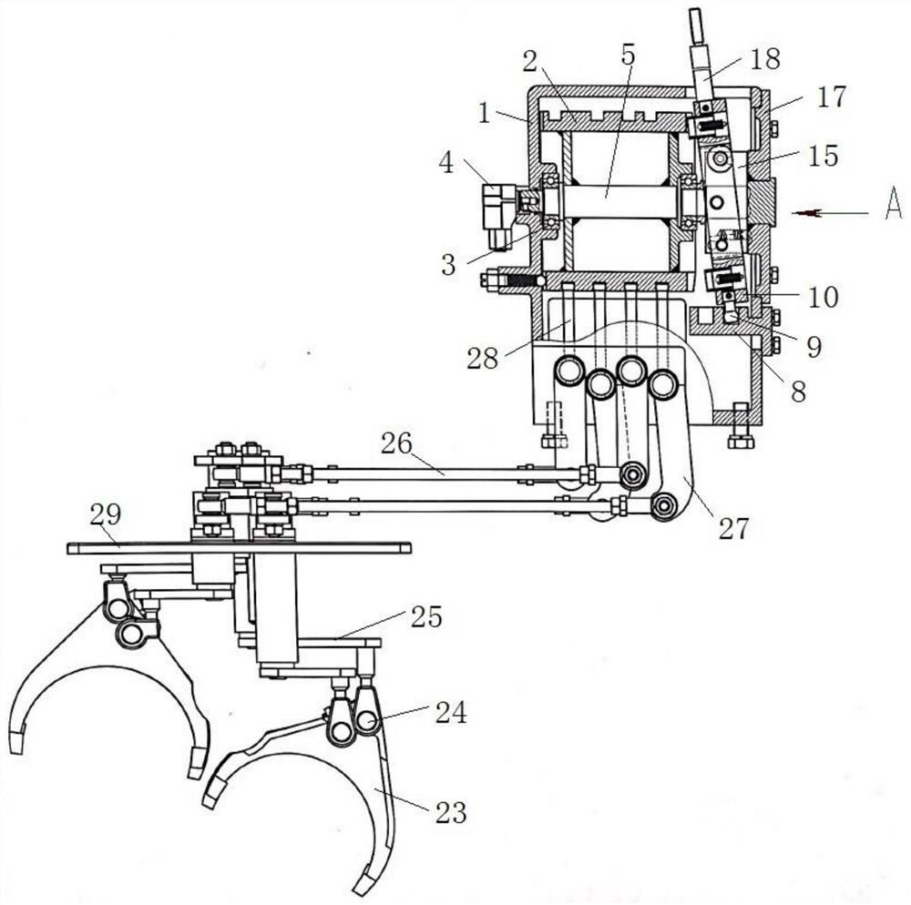
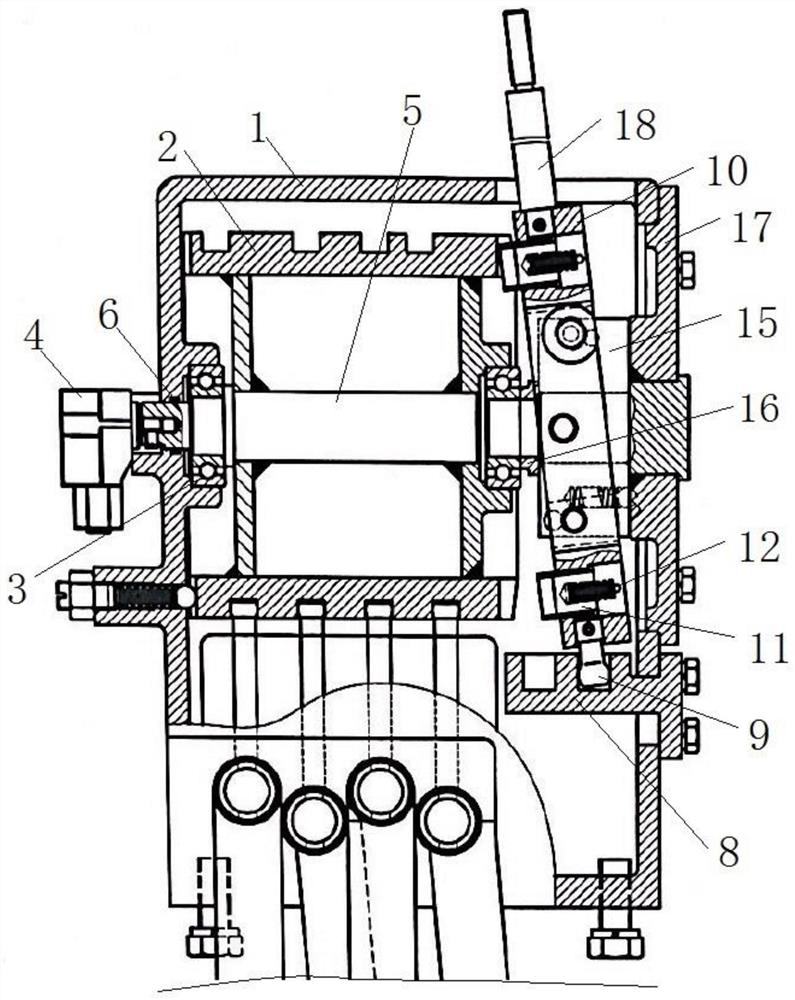
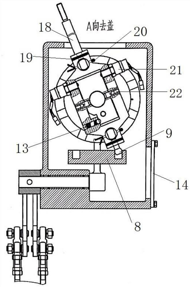
[0007] The present invention solves the problems in the related art that there are many pull rods in the gear control mechanism, the cumbersome operation causes the labor intensity of the staff to be high, and the inspection and maintenance of the shift fork is inconvenient. It proposes a dual-clutch preset gear control mechanism. The pin shaft cooperates with the gear slot on the cam to make the cam rotate forward and backward. Rotating a set angle can realize the preset of two gear positions at the same time, and the operation is more simple; by turning the swing block left and right to set the angle, it can be used to switch and add gears. Shift or downshift mode; after the upshift or downshift mode is selected by the swing block, the movement track of the lead rod in the limit block can be limited by swinging the joystick back and forth to realize upshift or downshift, and the operation is simple; In addition, when overhauling the shift fork assembly, you only need to disassemble the control cover, then you can take out the rocker arm assembly and replace the shift fork assembly, making the inspection and maintenance easier; finally, the angle sensor and the start switch can accurately identify Shifting action, making shifting more accurate

Method used


Image

  • Double-clutch preset gear control mechanism
  • Double-clutch preset gear control mechanism
  • Double-clutch preset gear control mechanism

Examples


Embodiment Construction

[0038] The following will clearly and completely describe the technical solutions in the embodiments of the present invention with reference to the accompanying drawings in the embodiments of the present invention. Obviously, the described embodiments are only some, not all, embodiments of the present invention. The following description of at least one exemplary embodiment is merely illustrative in nature and in no way taken as limiting the invention, its application or uses. Based on the embodiments of the present invention, all other embodiments obtained by persons of ordinary skill in the art without creative efforts fall within the protection scope of the present invention.

[0039] It should be noted that the terminology used here is only for describing specific implementations, and is not intended to limit the exemplary implementations according to the present application. As used herein, unless the context clearly dictates otherwise, the singular is intended to include...


PUM


Abstract

The invention relates to the technical field of gear shifting control mechanisms, in particular to a double-clutch preset gear control mechanism. The double-clutch preset gear control mechanism comprises a cam assembly, an angle sensor, starting switches, a limiting block, a swing block, shifting fork assemblies and a control cover, the cam assembly comprises a cam, and a plurality of lead groovesand a plurality of gear grooves are formed in the cam; the limiting block is mounted below the cam assembly, and a limiting groove used for mounting a lead rod is formed in the limiting block; the swing block is connected with a control rod and the lead rod, and the swing block cooperates with the gear grooves through positioning pins at the two ends for gear shifting; the swing block can rotateleft and right to switch upshift and downshift; the shifting fork assemblies are mounted in the lead grooves of the cam through rocker arm assemblies; and the control cover is mounted on a gearbox body, and a pipe sleeve used for supporting the rocker arm assemblies is mounted on the control cover. Gear shifting and upshift and downshift switching are easy and convenient to operate, and the shifting fork assemblies are more convenient to overhaul.

Description

technical field [0001] The invention relates to the technical field of shifting operating mechanisms, in particular to a dual-clutch preset gear operating mechanism. Background technique [0002] For tractors, the existing control mechanism is that the main and auxiliary transmission shift levers act on the main and auxiliary gear selection / shift rods, and are connected to the shift dial through the transmission shaft of the main and auxiliary transmission shift shafts. The shifting head moves the shifting block connected with the shifting fork on the shifting fork shaft or directly shifting the shifting fork, and the shifting fork moves the meshing sleeve or synchronous ring connected with the gear to realize gear shifting. [0003] However, this manipulation has the following disadvantages: [0004] 1) There are many tie rods, which are exposed outside the gearbox body, unsightly and fragile; [0005] 2) The operation is cumbersome and the labor intensity of the staff is...

Claims


Application Information

Patent Timeline
Patent Type & Authority Applications(China)
IPC IPC(8): F16H63/08F16H63/30
CPCF16H63/08F16H63/30F16H2063/025
Inventor 汪昌华刘兰新王占义王娟娟宋美华
Owner JIANGSU WORLD AGRI MACHINERY
Learn More