
A pressure sensing electromechanical pressure detection device

An air pressure detection and sensing technology, which is applied in the direction of measuring devices, measuring fluid pressure, instruments, etc., can solve the problem of low measurement accuracy, achieve centralized and accurate measurement results, and avoid the effect of excessive local pressure

Active Publication Date: 2021-10-08
JIANGSU SECURITY TECH CARRER ACADEMY
View PDF18 Cites 0 Cited by
  • Summary
  • Abstract
  • Description
  • Claims
  • Application Information

AI Technical Summary

Problems solved by technology

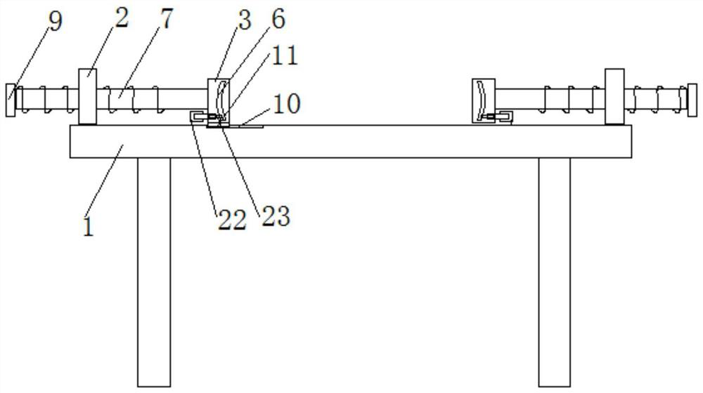
[0004] The purpose of the present invention is to provide a pressure sensing electromechanical pressure detection device, which solves the problem of low measurement accuracy due to different clamping surface shapes

Method used


Image

  • A pressure sensing electromechanical pressure detection device
  • A pressure sensing electromechanical pressure detection device
  • A pressure sensing electromechanical pressure detection device

Examples


Embodiment 1

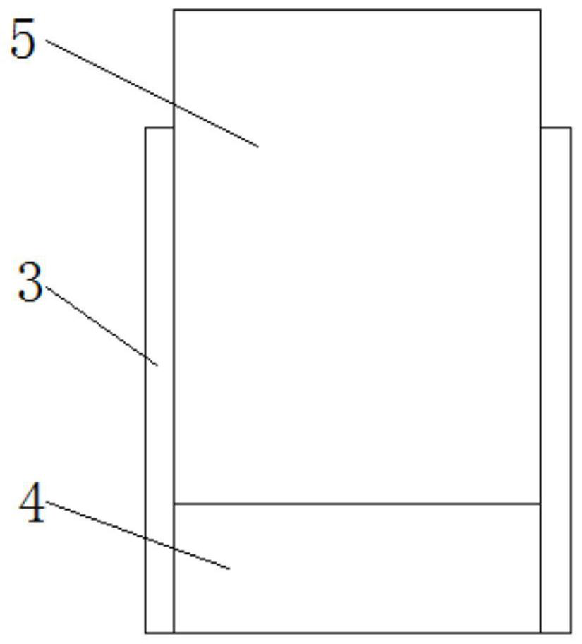
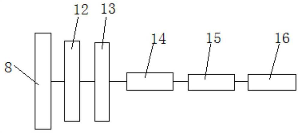
[0029] A pressure sensing type electromechanical pressure detection device, such as Figure 1-3 As shown, it includes an operating table 1, which is used to place fixtures and workpieces to be measured; it also includes a fixed block 2 arranged on the surface of the operating table 1, and two fixed blocks 2 are provided, and the two fixed blocks 2 are respectively fixed on the On both sides of the surface of the console 1, the side of the fixed block 2 is provided with threaded holes, and also includes a rectangular detection clip 3. There are two rectangular detection clips 3, which are respectively arranged between the two fixed blocks 2. The rectangular detection clip 3 is Hollow rectangular block, two rectangular detection clips 3 are respectively provided with notches 4 on the opposite sides, the notches 4 are provided with push-pull baffles 5, the push-pull baffles 5 are movably connected with both sides of the notch 4, and the push-pull baffles 5 can be Vertically stret...

Embodiment 2

[0034] Further, on the basis of embodiment 1, such as Figure 4 As shown, the push-out mechanism includes a push-out rod 23 arranged horizontally, one end of the push-out rod 23 is fixedly connected with the arc-shaped detection clip 6, and the other end of the push-out rod 23 passes through the side wall of the rectangular detection clip 3 and is threadedly connected with a screw rod 17. It also includes a hollow fixed rod 18, the screw rod 17 is inserted into the hollow fixed rod 18, the end of the screw rod 17 is also sleeved with a first bevel gear 19, and the hollow fixed rod 18 is provided with a first bevel gear 19 meshing with the first bevel gear. Two bevel gears 20, the outer wall of the hollow fixed rod 18 is also provided with a rotary handle 21, and the rotary handle 21 passes through the side wall of the hollow fixed rod 18 and is connected with the second bevel gear 20; Groove 25, the both sides of screw mandrel 17 are provided with retractable stop rod 24, and ...


PUM


Abstract

The invention discloses a pressure-sensing type electromechanical pressure detection device, which comprises an operation table and two fixed blocks arranged on the operation table, two hollow rectangular detection clips are arranged between the two fixed blocks, the rectangular detection clips The side is fixedly connected to the threaded rod, and the other end of the threaded rod passes through the fixed block and is threadedly connected with it; each hollow rectangular detection clip is slidingly provided with an arc-shaped detection clip, and one side of each arc-shaped detection clip is also provided with a push-out mechanism , the push-out mechanism is set through the side wall of the rectangular detection clip and can push the curved detection clip out of the gap on the rectangular detection clip, and also includes a pressure sensing module, and each push-pull baffle and the arc detection clip are provided with the described Pressure sensing module; this device enables both square workpieces and arc-shaped workpieces to be in close contact with the fixture during the air pressure detection process, avoiding the occurrence of excessive local pressure, and making the measurement results more concentrated and accurate.

Description

technical field [0001] The invention belongs to the technical field of air pressure detection devices, and in particular relates to a pressure-sensing electromechanical pressure detection device. Background technique [0002] In electromechanical operation, when using CNC machine tools to process the shell or middle frame of electronic products (such as mobile phones, tablet computers, etc.), fixtures are usually used to clamp the workpiece to be processed on the positioning surface of the fixture, and then use CNC The tool of the machine tool processes the workpiece to realize the processing of the workpiece. [0003] The fixtures in the prior art need to detect the air pressure held by them during the working process. During the air pressure detection process, due to the different shapes of the clamping surfaces, there is a loose connection between the clamping surface and the working surface during the air pressure measurement process. As a result, the local pressure is ...

Claims


Application Information

Patent Timeline
Patent Type & Authority Patents(China)
IPC IPC(8): G01L11/00
CPCG01L11/00
Inventor 刘春夏蓉花窦万军
Owner JIANGSU SECURITY TECH CARRER ACADEMY
Learn More