Marking machine

A marking machine and marking head technology, applied in the field of marking machines, can solve the problems of low efficiency, easy injury to operators, manual feeding, etc., and achieve the effects of improving safety performance, reducing operation difficulty, and improving work efficiency

Pending Publication Date: 2020-11-06
日照汇丰电子有限公司
View PDF0 Cites 0 Cited by
  • Summary
  • Abstract
  • Description
  • Claims
  • Application Information

AI Technical Summary

Problems solved by technology

At present, the conventional marking machine needs manual feeding, and it needs to be held by hand during the marking process, and then the marking machine is started to mark
This operation is not only inefficient, but also easily hurts the hands of the operator.

Method used


Image

  • Marking machine
  • Marking machine
  • Marking machine

Examples


Embodiment Construction

[0022] The present invention will now be described in further detail in conjunction with the accompanying drawings, which are simplified schematic diagrams, only schematically illustrating the basic structure of the present invention, and therefore only show the configurations related to the present invention.

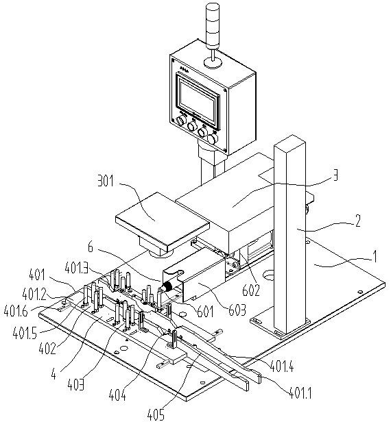
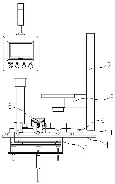
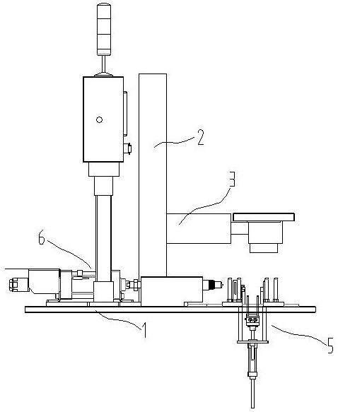
[0023] Such as Figure 1-5 As shown, a marking machine includes a workbench 1, a bracket 2, and a marking head 3. The workbench 1 is provided with a positioning device 4, a conveying device 5, and an adjustment device 6; the positioning device 4 is located on the The workbench 1 includes two positioning assemblies 401 arranged parallel to each other. A cavity is provided at the workbench 1 between the two positioning assemblies 401. The two positioning assemblies 401 are sequentially provided with upper Material station 402, adjustment station 403, marking station 404, and discharge station 405.

[0024] The conveying device 5 is located below the positioning device 4...


PUM


Abstract

The invention discloses a marking machine which comprises a working table, a support and a marking head. The working table is further provided with a locating device, a conveying device and an adjusting device. The locating device is located on the working table and comprises two locating assemblies which are arranged in parallel. A cavity is formed in the portion, between the two locating assemblies, of the working table. Feeding stations, adjusting stations, marking stations and discharging stations are sequentially arranged on the two locating assemblies from left to right. The conveying device is located below the locating device and comprises a conveying portion. The conveying portion is located in the cavity between the two locating assemblies. The conveying portion is provided withthree taking grooves which correspond to the feeding stations, the adjusting stations and the marking stations. According to the marking machine, the problem of manual feeding of the marking machine is solved, multi-station continuous work is adopted, automatic feeding and discharging are achieved, an operator only needs to place workpieces in a supply area, and the working efficiency is improved.

Description

technical field [0001] The invention relates to the technical field of marking an air conditioner liquid storage device, in particular to a marking machine. Background technique [0002] After the air-conditioning reservoir is manufactured, it must be coded and marked, which requires a marking machine to operate. At present, the conventional marking machine needs manual feeding, and it needs to be held by hand during the marking process, and then the marking machine is started to mark. This operation is not only inefficient, but also easily hurts the hands of the operator. Contents of the invention [0003] The technical problem to be solved by the present invention is: to overcome the above problems, provide a marking machine that can automatically feed, mark, and discharge materials, and the operator only needs to put the liquid storage device in the feeding area. [0004] The technical solution adopted by the present invention to solve the technical problem is: a mark...

Claims


Application Information

Patent Timeline
Patent Type & Authority Applications(China)
IPC IPC(8): B41J11/00B41J3/407
CPCB41J3/4073B41J11/0045
Inventor 薛贸芮路祥
Owner 日照汇丰电子有限公司
Why Eureka
Try Eureka