Coiled material ironing roller device of high-speed cold-rolling mill

A technology for ironing rolls and cold rolling mills is applied in the field of aluminum sheet processing to achieve the effect of simplifying the constant pressure control system

Pending Publication Date: 2020-11-06
洛阳泰盟机械制造有限公司
View PDF0 Cites 0 Cited by
  • Summary
  • Abstract
  • Description
  • Claims
  • Application Information

AI Technical Summary

Problems solved by technology

Since the mathematical modeling of the screed roller motion mechanism is nonlinear, the existing screed roller devices have not been able to solve this problem well

Method used


Image

  • Coiled material ironing roller device of high-speed cold-rolling mill
  • Coiled material ironing roller device of high-speed cold-rolling mill

Examples


Embodiment Construction

[0014] Preferred embodiments of the present invention are described below with reference to the accompanying drawings. Those skilled in the art should understand that these embodiments are only used to explain the technical principles of the present invention, and are not intended to limit the protection scope of the present invention.

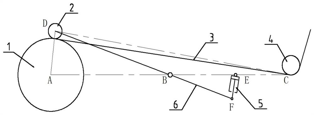
[0015] A high-speed cold rolling mill coil ironing roll device, such as Figure 1-2 As shown, the coiled material 3 is wound up on the winding roller 1 after being tightened by the angle-wrapping roller 4, and the ironing roller 2 is installed on one end of the lever 6, where the lever 6 is equivalent to the arm of the ironing roller described in the background technology . The projection point B of the axis of rotation of the lever 6, the projection point A of the winding roller 1 axis, and the projection point C of the coil 3 at the tangent away from the angle wrapping roller 4, the three projection points are located on the same straight l...


PUM


Abstract

Provided is a coiled material ironing roller device of a high-speed cold-rolling mill. A coiled material is tightened by a corner wrapping roller and then wound on a winding roller, and an ironing roller is disposed at one end of a lever; a projection point B of a rotary axis of the lever, a projection point A of an axis of the winding roller and a projection point C of the coiled material at a position away from a tangent of the corner wrapping roller are located on the same straight line; a projection point of an axis of the ironing roller is D; and in terms of length, AB=BC, and DB=AB+L, wherein L is less than or equal to 80 mm and greater than or equal to 35 mm. With a moving trajectory of a winding and cutting point as an object of study, the ironing roller can relatively constantly press the position 3-5 cm away from the winding and cutting point, thereby realizing the aim of the optimum coiled material winding effect. A constant pressure mechanism can exert constant pressure onthe coiled material by the ironing roller only by shaking an oil cylinder to output constant thrust, thereby simplifying a constant pressure control system of the ironing roller device.

Description

technical field [0001] The invention relates to the technical field of aluminum plate processing, in particular to a coil ironing roll device of a high-speed cold rolling mill. Background technique [0002] The ironing roller device is the equipment that needs to be used in the processing of aluminum coils. Its main function is to assist the coiler to make the coils tight and neat, and to squeeze out the air gap. The existing ironing roller device usually adopts the structural form of a swing arm oil cylinder, so that the ironing roller is constantly pressed on the coil. As the coil diameter increases, the pressing position of the ironing roller on the coil changes. According to the installation position of the arm of the ironing roller, the pressing position of the ironing roller is either gradually away from the coil tangent point, or gradually close to it. The volume cut point cannot be constant. Practice has proved that when the pressing position of the ironing roller ...

Claims


Application Information

Patent Timeline
Patent Type & Authority Applications(China)
IPC IPC(8): B21C47/32
CPCB21C47/323
Inventor 王守庆卜宇
Owner 洛阳泰盟机械制造有限公司
Why Eureka
Try Eureka