
Ophthalmic function inspection equipment based on slit lamp platform

A functional inspection and slit lamp technology, which is applied to eye testing equipment, ophthalmoscopes, medical science, etc., can solve problems such as low efficacy of slit lamps, interference with the fineness of ophthalmic function inspections, and blurred light curtains, so as to improve relaxation and smoothness. The effect of turning efficiency

Inactive Publication Date: 2020-11-06
淮安市第二人民医院(淮安仁慈医院)
View PDF0 Cites 2 Cited by
  • Summary
  • Abstract
  • Description
  • Claims
  • Application Information

AI Technical Summary

Problems solved by technology

[0004] Aiming at the deficiencies in the prior art, the purpose of the present invention is to provide an ophthalmic function inspection device based on a slit lamp platform to solve the problem of astigmatism caused by diffuse spacing lighting and light guide eyeballs and lenses forming the guiding effect of autonomous observation. The light curtain is blurred, and the detection deviation of the eyeball and lens is relatively large, which leads to a decrease in the subsequent test data of the iris and cornea, which interferes with the focus of the slit lamp lighting conditions and the subsequent luminosity, resulting in subsequent lens barrels. The amount of data feedback is poor, which interferes with the fineness of ophthalmic functional examination, thus causing the efficacy of the slit lamp to be suppressed, and the patient's and easy to be misdiagnosed.

Method used


Image

  • Ophthalmic function inspection equipment based on slit lamp platform
  • Ophthalmic function inspection equipment based on slit lamp platform
  • Ophthalmic function inspection equipment based on slit lamp platform

Examples


Embodiment 1

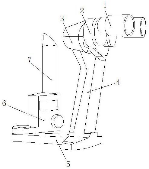
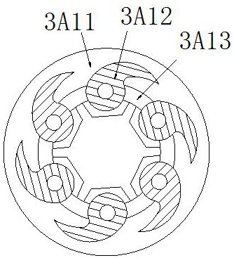
[0032] see Figure 1-Figure 6, the present invention provides an ophthalmic function inspection device based on a slit lamp platform, the structure of which includes: an eyepiece tube 1, a lens left wheel 2, a rotor beam shielding cone 3, a hand grip 4, a counterweight base block 5, and a data display 6. Antenna mast 7, the rotor beam shielding cone 3 is nested on the left side of the left lens wheel 2 and penetrates each other, the lens barrel 1 is inserted on the right side of the left lens wheel 2 and is perpendicular to each other, the The rotor beam shielding cone 3 is nested on the top of the hand grip 4, the hand grip 4 is welded to the upper right corner of the counterweight base block 5 and is perpendicular to each other, and the data display 6 is electrically connected to the antenna mast 7 , the data display 6 is nested in the upper left corner of the counterweight base block 5, and the rotor beam shading cone 3 is provided with a beam lamp bead ring 3A, a rotor con...

Embodiment 2

[0039] see Figure 1-Figure 6 , the present invention provides an ophthalmic function inspection device based on a slit lamp platform, which is the same as in Embodiment 1 in other respects, except that:

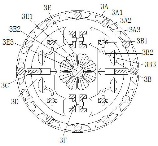
[0040] see figure 2 The iris cover plate 3E is composed of a light guide strip 3E1, a base fan plate 3E2, and a column core spacer 3E3. The light guide strip 3E1 is embedded in the base fan plate 3E2 and is on the same vertical plane. The base fan plate 3E2 and the column core pad 3E3 are nested together and the axes are collinear. The black block of the axis of the column core pad 3E3 is pressed against the light guide strip 3E1 to ensure that the outer ring light curtain wraps the black spot for easy observation and improvement. Attention, ensuring the comfort of the lens and eyeballs, adjusting and observing the nursing effect.

[0041] see Figure 6 The light guide strip 3E1 is composed of a grid frame plate 3E11, a trapezoidal reflective plate 3E12, and a button sea...


PUM


Abstract

The invention discloses ophthalmic function inspection equipment based on a slit lamp platform. The ophthalmic function inspection equipment structurally comprises an eyepiece sleeve, a lens left wheel disc, a rotor beam shielding conical barrel, a handheld grip, a counterweight base block, a data display and an antenna column rod. A light receiving focusing matching effect is formed through a beam lamp bead ring and a rotor convex lens frame to avoid the fuzzy observation of astigmatism, so that the operation that the whole lens cone stretches, clamps and retracts a shading nipper plate and then shoots into the refracted beam line is improved; it is guaranteed that subsequent passing light and distance light adjust crystalline lens, and conical channel divergence iris examination adjusting effect is obtained through projection of a black point column core of an iris cover disc, so that the composite adjustment operation of a rotor ball block and a convex lens seat is singly performedon the cornea alignment after the iris detection and the crystalline lens adjustment; and the whole eye socket is effectively detected and adjusted step by step, the light scattering phenomenon is avoided, and the eyeball relaxing and sliding efficiency is improved.

Description

technical field [0001] The invention relates to ophthalmic function inspection equipment based on a slit lamp platform, which belongs to the field of medical equipment. Background technique [0002] The adjustment of the slit lamp to ophthalmic color weakness and dispersion can effectively adjust the spectrum to illuminate the eyeball flexibly, ensure the comfort of ophthalmological function examination, and improve the portable operation effect of the equipment platform, so that the superposition accuracy of the lens of the equipment can be effectively popularized and applied , so that optical equipment and medical equipment can be effectively combined. The shortcomings of the current technology that need to be optimized are: [0003] When the diffuse spacing lighting light guide eyeball and lens form the guiding effect of independent observation, the light curtain will be blurred due to the patient's astigmatism, and the detection deviation of the eyeball and lens will be ...

Claims


Application Information

Patent Timeline
IPC IPC(8): A61B3/135A61B3/13A61B3/00G02B27/00
CPCA61B3/0008A61B3/0016A61B3/132A61B3/135G02B27/00
Inventor 孙昊
Owner 淮安市第二人民医院(淮安仁慈医院)
Learn More