Eureka AIR delivers breakthrough ideas for toughest innovation challenges, trusted by R&D personnel around the world.

Parafoil system obstacle avoidance flight path planning method and system

A track planning and parafoil technology, applied in general control systems, control/regulation systems, three-dimensional position/course control, etc.

Active Publication Date: 2020-11-03
HUAIYIN INSTITUTE OF TECHNOLOGY
View PDF3 Cites 4 Cited by
  • Summary
  • Abstract
  • Description
  • Claims
  • Application Information

AI Technical Summary

Problems solved by technology

The above-mentioned segment homing algorithm adopts the same objective function, which converts the trajectory planning problem into the optimization problem of entry point (Entry Point) parameters. Although the algorithms adopted are different in terms of convergence speed, the results obtained are roughly the same can meet the requirements of precision landing and headwind landing

Method used


Image

  • Parafoil system obstacle avoidance flight path planning method and system
  • Parafoil system obstacle avoidance flight path planning method and system
  • Parafoil system obstacle avoidance flight path planning method and system

Examples


Embodiment 1

[0117] In this embodiment, the track planning of the parafoil system is carried out under the condition of barrier-free, and the objective function is:

[0118] J=f 1 J 1 + f 2 J 2 + f 3 J 3

[0119] That is, without considering the safety obstacle avoidance index J 4 , and compared with the optimal control homing algorithm based on Gaussian pseudospectral method and the segmented homing algorithm based on genetic algorithm. Among them, the optimal track algorithm based on pseudo-spectrum refers to the literature: (1) Gao Haitao, Zhang Limin, Sun Qinglin, etc. Fault-tolerant design of homing trajectory of parafoil system based on pseudo-spectral method [J]. Control Theory and Application. 2013 (06) :702-708; (2) Luo Shuzhen, Sun Qinglin, Tan Panlong, et al. Complex multi-constraint trajectory planning of parafoil system based on Gaussian pseudospectral method[J].Acta Aeronautics Sinica.2017(03): 220-230. The segmented track algorithm based on genetic algorithm refers t...

Embodiment 2

[0122] In this embodiment, the obstacle avoidance track planning of the parafoil system is carried out in the presence of obstacles, and the objective function is:

[0123] J=f 1 J 1 +f 2 J 2 +f 3 J 3 +f 4 J 4

[0124] There are 3 mountain peaks in the parafoil flying area in this embodiment, and their center coordinates are respectively (2000,1000), (1000,3000), (400,1500), and the peak heights are respectively 2500, 2000, 1800. x si 550, 480, 380 respectively, the preset safety distance R safe It is 50 meters, and all the other airdrop conditions are exactly the same as the barrier-free situation in embodiment one. Considering that the segmented homing method has no obstacle avoidance capability, but the pseudo-spectral method has the obstacle avoidance planning capability, so this embodiment compares the optimal obstacle avoidance based on the pseudo-spectral method and the optimal segmented constant value obstacle avoidance navigation disclosed by the present inv...

Embodiment 3

[0131] This embodiment discloses a system for implementing the obstacle avoidance track planning method of the parafoil system in Embodiment 2, as shown in Figure 11, including:

[0132] Parafoil reduced-price particle model building module 1 is used to establish the reduced-order particle model of parafoil under the wind fixed coordinate system:

[0133]

[0134] Where (x, y, h) are the position components of the parafoil system in the x direction, y direction and vertical direction of the horizontal plane in the wind fixed coordinate system, v s is the horizontal velocity of the parafoil system, v z is the velocity in the vertical direction, ψ is the heading angle, is the heading rate, and u is the control value corresponding to the asymmetric downward deflection of the parafoil;

[0135] The mountain obstacle model building module 2 is used to establish the mountain obstacle model in the parafoil flight area:

[0136]

[0137] Among them, h(x, y) is the height val...


PUM


Abstract

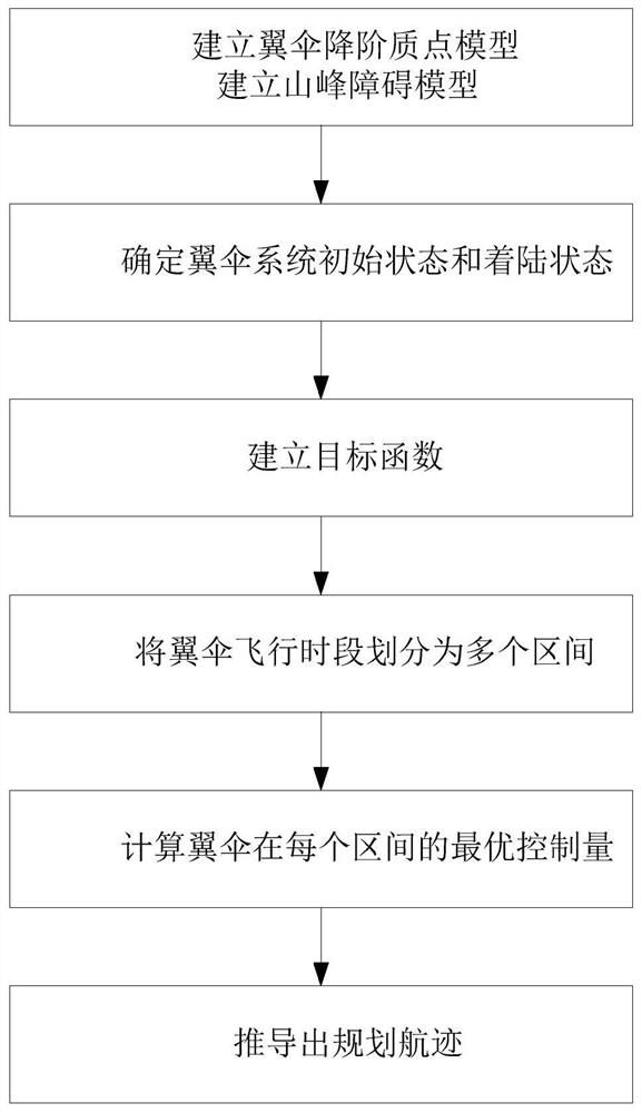
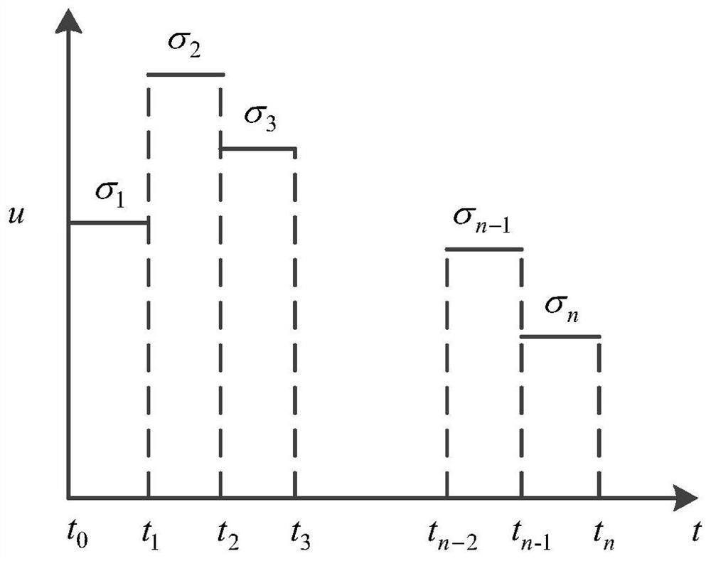
The invention discloses a parafoil system obstacle avoidance flight path planning method, which comprises the steps of 1, establishing a parafoil order reduction particle model under a wind fixed coordinate system, and modeling a peak obstacle; 2, determining the position and the course angle of the parafoil system at the initial moment of air drop, the expected position and the expected course angle at the landing moment, and the maximum pull-down amount of a parafoil control rope; 3, combining landing point horizontal position errors, landing point course errors, control energy consumption and safety obstacle avoidance indexes to establish an objective function of parafoil system route planning; 4, dividing a parafoil flight period into n adjacent intervals, and taking a constant value of a control quantity in each sub-interval to control a parafoil system; 5, solving the optimal control quantity of each interval in the parafoil flight period, and enabling the objective function value to be the minimum value; and 6, obtaining a planned route according to the optimal control quantity sequence and the initial state and speed of the parafoil. The planned flight path obtained by themethod meets the requirements of accurate landing point position, headwind landing and low flight path energy consumption, and can bypass obstacles such as mountains and the like.

Description

technical field [0001] The invention belongs to the technical field of parafoil track planning, and in particular relates to a method and system for planning an obstacle-avoiding track when obstacles exist in the flight area of ​​a parafoil system. Background technique [0002] The stamped parafoil is a flexible aircraft made of textile materials. After the parafoil is opened, the air enters the air chamber through the cutout at the front edge of the parafoil, forming a stagnation pressure in the air chamber, so that the parafoil can maintain a relatively stable wing shape and generate lift. and resistance, so the parafoil has a high lift-to-drag ratio, excellent gliding performance and controllability. Pulling the trailing edge of the canopy can adjust the flying direction and speed of the parafoil to achieve precise landing, which overcomes the shortcomings of the traditional circular parachute's flight trajectory floating with the wind and large spread of landing points. ...

Claims


Application Information

Patent Timeline
IPC IPC(8): G05D1/10G05B13/04G05B13/02
CPCG05D1/105G05D1/106G05B13/042G05B13/0265
Inventor 陈奇石春雪郑霞李忠华郭丽杨锦会朱祥耿砚文王大友周进
Owner HUAIYIN INSTITUTE OF TECHNOLOGY
Why Eureka
Eureka Blog
Learn More