Spring type piezoelectric air pump

A spring-type, electric pump technology, applied in the direction of variable-capacity pump components, pumps, pump components, etc., can solve the problems of limited deformation capacity of diaphragm piezoelectric vibrators and poor gas output effect, so as to improve the working effect, Simple structure and small volume

Active Publication Date: 2020-11-03
CHANGCHUN UNIV
View PDF5 Cites 1 Cited by
  • Summary
  • Abstract
  • Description
  • Claims
  • Application Information

AI Technical Summary

Problems solved by technology

The diaphragm piezoelectric vibrator has limited deformation ability, poor output effect on gas, and cannot work at higher frequencies

Method used


Image

  • Spring type piezoelectric air pump
  • Spring type piezoelectric air pump
  • Spring type piezoelectric air pump

Examples


Embodiment 1

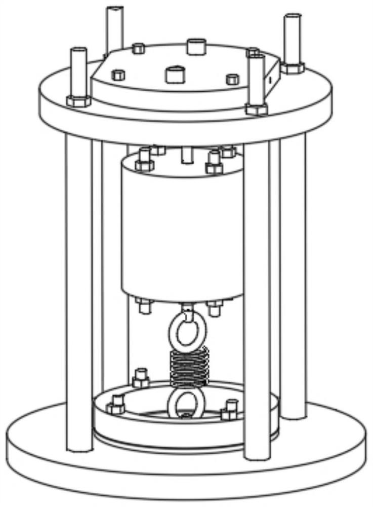
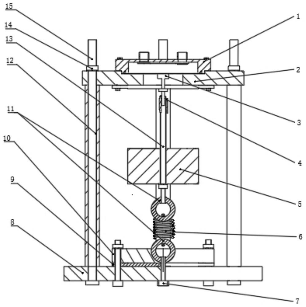
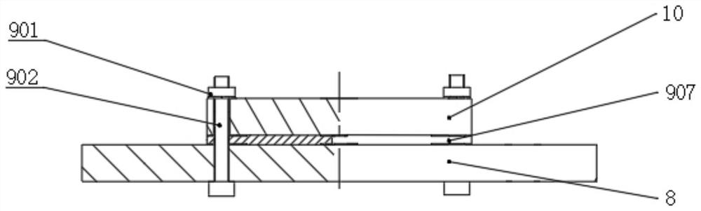
[0021] See Figure 1-5 , a spring-type piezoelectric pump, including a base 8, the base 8 is a disc-shaped structure, the top surface of the base 8 is provided with a positioning ring 10, the positioning ring 10 is a circular structure, the base 8 The axis coincides with the axis of the positioning ring 10. A vibrator fixing structure 9 is provided between the positioning ring 10 and the base 8. The vibrator fixing structure 9 includes third bolts 902. The positioning ring 10 is fixed on the base by several third bolts 902. 8, the third bolt 902 is covered with a first nut 901, and a first piezoelectric vibrator 907 is also provided between the positioning ring 10 and the base 8, and the top edge of the base 8 is in a circular array Be provided with some columns 12, described column 12 is circular tubular structure, and the top of all columns 12 is provided with lower cavity 2 jointly, and described lower cavity 2 is installed on the column 12 by screw rod 15, and the top of d...

Embodiment 2

[0024]The difference from Embodiment 1 is that the bottom of the lower cavity 2 is provided with a second piezoelectric vibrator 903, and the second piezoelectric vibrator 903 is installed on the lower cavity 2 through a second bolt 904. The piezoelectric vibrator 903 is installed on the joint 3 through the second nut 906. By setting the second piezoelectric vibrator 903 as another driving source, the second piezoelectric vibrator 903 directly drives the joint 3 to vibrate at a close distance, and then drives the entire device to operate. , the working efficiency of the whole device can be increased, and the second piezoelectric vibrator 903 cooperates with the first piezoelectric vibrator 907 to further expand the amplitude and further improve the working effect of the whole device.

[0025] The working principle of Embodiment 1-2: the present invention uses the first piezoelectric vibrator 907 as the driving source, and then uses the spring 6 to cooperate with the resonant ro...


PUM


Abstract

The invention discloses a spring type piezoelectric air pump. The spring type piezoelectric air pump comprises a base, wherein a positioning ring is arranged on the top end face of the base, a first piezoelectric vibrator is further arranged between the positioning ring and the base, a plurality of stand columns are arranged on the edge of the top end of the base in a circular array mode, the topends of all the stand columns are jointly provided with a lower cavity body, a clamping groove is formed in the top end of the lower cavity body, a cavity body is formed inside the clamping groove, the cavity body comprises an upper cavity body, the upper cavity body is formed inside the clamping groove through a sealing ring, a metal film matched with the clamping groove is fixedly connected to the bottom end of the sealing ring, a joint is fixedly connected to the bottom end of the metal film, the bottom end of the joint is connected with a resonance rod through a tightening ring, and a spring is arranged between the resonance rod and the positioning ring. According to the spring type piezoelectric air pump, through the arrangement of a mass block, the resonance frequency of the whole device is changed, work under the low-frequency work condition of 400 HZ or below can be achieved, work under the high-frequency work condition of 400 HZ or above can also be achieved, and no magnetic interference is generated or received at all.

Description

technical field [0001] The invention relates to the technical field of electric pumps, in particular to a spring-type piezoelectric electric pump. Background technique [0002] The air diaphragm pump is a new type of conveying machinery, which uses compressed air as the power source. It can pump all kinds of corrosive liquids, liquids with particles, high viscosity, volatile, flammable, and highly toxic liquids. . The main features of this pump are pneumatic diaphragm pump, stainless steel pneumatic diaphragm pump, QBY pneumatic diaphragm pump. [0003] In the two symmetrical working chambers of the pump, each is equipped with an elastic diaphragm to form two independent chambers. The intermediate shaft integrates the two diaphragms into one body. The air distribution valve controls the pressurization of each chamber. After the air enters the gas distribution valve, it pushes one side of the diaphragm, driving the two diaphragms connected by the link to move synchronously....

Claims


Application Information

Patent Timeline
Patent Type & Authority Applications(China)
IPC IPC(8): F04B45/047F04B39/00
CPCF04B45/047F04B39/00
Inventor 田晓超李庆华赵昌龙贺春山赵剑李志瑶杨凤双闻人锴琦
Owner CHANGCHUN UNIV
Why Eureka
Try Eureka