
Carbon coating device for solid-state silicon-carbon-lithium-tantalum battery negative electrode material

A battery negative electrode, silicon carbon lithium technology, applied to battery electrodes, transportation and packaging, mixers with rotating stirring devices, etc., can solve the problems of poor carbon coating efficiency and coating effect, and reduce battery production efficiency. Accelerate carbon coating efficiency, improve efficiency and coating effect, good coating effect

Inactive Publication Date: 2020-11-03
PENGSHENG GUONENG (SHENGZHEN) NEW ENERGY GRP CO LTD
View PDF8 Cites 0 Cited by
  • Summary
  • Abstract
  • Description
  • Claims
  • Application Information

AI Technical Summary

Problems solved by technology

[0009] The purpose of the present invention is to provide a carbon coating device for the anode material of solid silicon carbon lithium tantalum battery, to solve the problem of poor carbon coating efficiency and coating effect in the above background technology, which greatly reduces the production efficiency of the battery

Method used


Image

  • Carbon coating device for solid-state silicon-carbon-lithium-tantalum battery negative electrode material
  • Carbon coating device for solid-state silicon-carbon-lithium-tantalum battery negative electrode material
  • Carbon coating device for solid-state silicon-carbon-lithium-tantalum battery negative electrode material

Examples


Embodiment 1

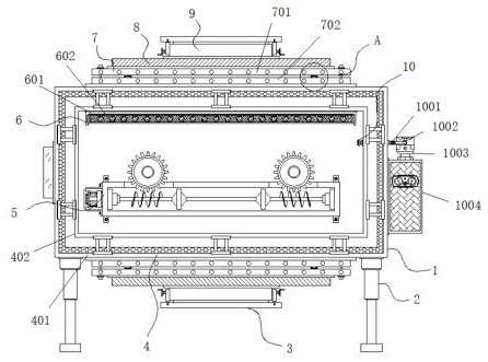
[0036] Example 1: See Figure 1-7 , a solid silicon carbon lithium tantalum battery negative electrode material carbon coating device, including a coating tank 1, a leg 2, a discharge port 3 and a feeding port 9, the four corners of the bottom end of the coating tank 1 are fixedly connected with the leg 2 , the bottom of the coating tank 1 is provided with a discharge port 3, the outer wall of the coating tank 1 is provided with a thermal insulation structure 4, and the top of the coating tank 1 is provided with a flue gas treatment structure 6, and the top of the coating tank 1 A top cover 8 is provided, and a disassembly and maintenance structure 7 is arranged between the top cover 8 and the coating tank 1. The top of the top cover 8 is provided with a feeding port 9, and one side of the coating tank 1 is provided with an anti-oxidation mechanism 10. The front end of the tank 1 is provided with an opposing stirring mechanism;

[0037] see Figure 1-7, a carbon coating devi...

Embodiment 2

[0041] Embodiment 2: The heat preservation structure 4 is composed of an outer shell 401, an inner shell 402, a hollow cavity 403, a support block 404 and a heat-insulating rock wool board 405. The outer shell 401 is arranged at one end of the outer wall of the coating tank 1, and the inner shell 402 is set on the other end of the outer wall of the cladding tank 1, the outer casing 401 and the inner casing 402 are provided with a hollow cavity 403, the inside of the hollow cavity 403 is uniformly provided with a support block 404, and one end of the hollow cavity 403 is fixedly connected with Thermal insulation rock wool board 405;

[0042] Specifically, such as figure 1 with Figure 7 As shown, the heat-insulating rock wool board 405 provided inside the outer shell 401 and the inner shell 402 can isolate the temperature conduction between the inside of the coating tank 1 and the outside world, thereby achieving the effect of heat preservation, saving energy, and meeting the ...

Embodiment 3

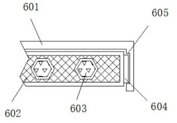
[0043] Embodiment 3: The flue gas treatment structure 6 is composed of a fixing groove 601, a barbed wire 602, an activated carbon block 603, a locking block 604 and a locking groove 605. The fixing groove 601 is fixedly connected to the top of the inside of the coating tank 1, and the inside of the fixing groove 601 is set There is a barbed wire 602, and the inside of the barbed wire 602 is evenly embedded with activated carbon blocks 603, both sides of the barbed wire 602 are provided with blocks 604, and both sides of the fixed groove 601 are provided with card slots 605;

[0044] The clamping block 604 is embedded inside the clamping slot 605, and a clamping structure is formed between the clamping block 604 and the clamping slot 605;

[0045] Specifically, such as figure 1 with figure 2 As shown, using the adsorption properties of the activated carbon block 603, the impurities in the flue gas generated inside the coating tank 1 will be adsorbed by the activated carbon b...


PUM


Abstract

The invention discloses a solid-state silicon-carbon-lithium-tantalum battery negative electrode material carbon coating device, and particularly relates to the technical field of battery processing equipment. The solid-state silicon-carbon-lithium-tantalum battery negative electrode material carbon coating device comprises a coating tank, support legs, a discharge port and a feeding port, the support legs are fixedly connected to four corners of the bottom end of the coating tank, and the discharge port is formed in the bottom end of the coating tank. By arranging the opposite stirring mechanism, the opposite stirring mechanism comprises the driving box, the driving box is fixed to the front end of the coating tank, the driving shaft is movably connected to the interior of the driving box, the servo motor is arranged on one side of the driving box, and during use, the servo motor is started and drives the driving shaft to rotate; the driving shaft drives the first gear and the secondgear to rotate oppositely through the driving blades arranged outside the driving shaft, so that the first stirring shaft and the second stirring shaft are driven to stir the interior of the driving shaft, the carbon coating efficiency can be improved, a centrifugal force generated during stirring can be prevented, and the carbon coating efficiency and the carbon coating effect are greatly improved.

Description

technical field [0001] The invention relates to the technical field of battery processing equipment, in particular to a carbon coating device for a solid silicon carbon lithium tantalum battery negative electrode material. Background technique [0002] Lithium battery anode materials need to be coated with carbon to overcome the defects of a single material, so that it has excellent electrochemical performance. Solid silicon carbon lithium tantalum batteries are a type of lithium batteries, so the battery anode materials need to use carbon in the production process. Coating devices, there are a variety of carbon coating devices for solid-state silicon-carbon lithium-tantalum battery anode materials on the market today, but there are still many problems and defects. [0003] In the process of realizing the present invention, the inventors have found that at least the following problems in the prior art have not been resolved: [0004] (1) The carbon coating efficiency and co...

Claims


Application Information

Patent Timeline
Patent Type & Authority Applications(China)
IPC IPC(8): B01F7/02B01F15/00B01F15/06H01M4/36H01M4/139B01D53/04
CPCH01M4/366H01M4/139B01D53/0407B01D2253/102B01D2258/0283B01F27/2322B01F27/60B01F35/00B01F35/322B01F35/10B01F35/90Y02E60/10
Inventor 朱少敏刘春燕
Owner PENGSHENG GUONENG (SHENGZHEN) NEW ENERGY GRP CO LTD
Learn More