
Pulsation type induction soap dispenser

A soap dispenser and soap liquid technology, which is applied in applications, brackets or dispensers, household appliances, etc., can solve the problems affecting the soap liquid extrusion flow, adhesion, soap liquid water evaporation and agglomeration, etc.

Pending Publication Date: 2020-11-03
제지앙인터하사인텔리전트테크놀로지컴퍼니리미티드
View PDF0 Cites 0 Cited by
  • Summary
  • Abstract
  • Description
  • Claims
  • Application Information

AI Technical Summary

Problems solved by technology

[0002] The induction soap dispenser generally senses the position of the human hand through the induction transmitter and the induction receiver, so as to control the driving of the soap pump to provide soap for the user. However, the existing induction soap dispenser is generally simple because of the soap outlet. Pipeline type, it is easy to leave part of the soap liquid in the soap liquid outlet after the soap liquid output is completed, it is easy to cause the soap liquid water to evaporate and agglomerate and adhere to the inner wall of the soap liquid outlet, causing the blockage of the soap liquid outlet and seriously affecting the soap liquid The extrusion flow rate is also high, and the agglomerated soap block on the inner wall of the soap liquid outlet is also prone to rush out of the soap liquid outlet along with the soap liquid, so that the solidified state soap liquid block and the liquid state soap liquid are taken by the user to wash hands, etc. Soap in liquid state can quickly foam and remove stains, while soap in solidified state needs to absorb water before it can be dissolved, so the soap block is also easy to adhere to the skin and difficult to scrub. Bring inconvenience and seriously affect the user experience

Method used


Image

  • Pulsation type induction soap dispenser
  • Pulsation type induction soap dispenser
  • Pulsation type induction soap dispenser

Examples


Embodiment Construction

[0026] The specific implementation manners of the present invention will be further described in detail below in conjunction with the accompanying drawings and embodiments. The following examples are used to illustrate the present invention, but are not intended to limit the scope of the present invention.

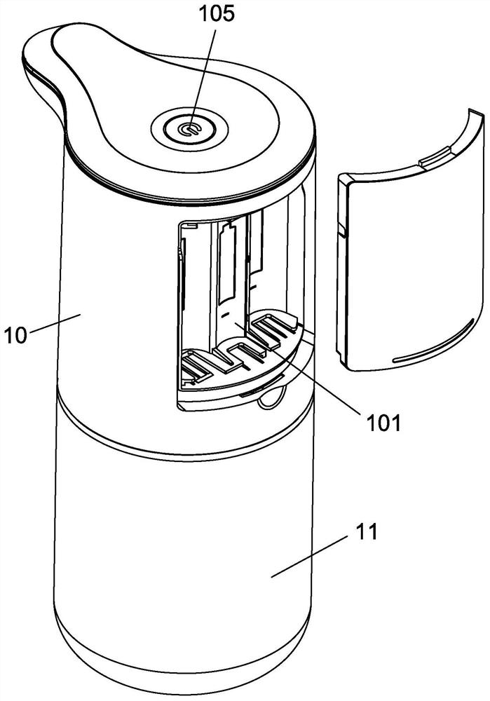
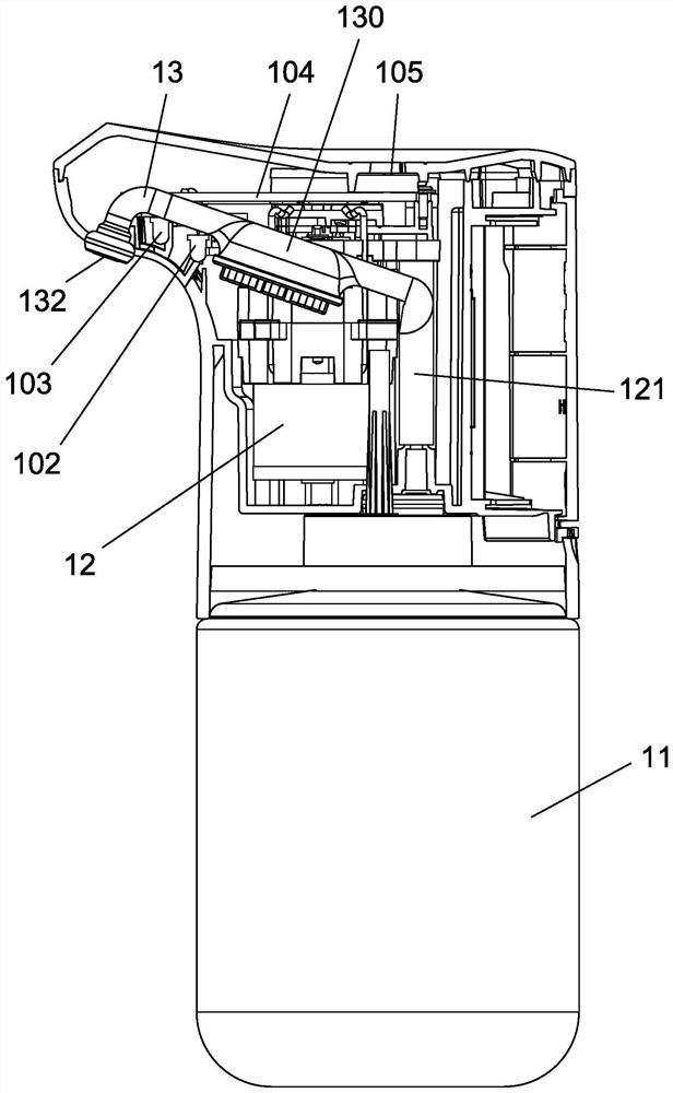
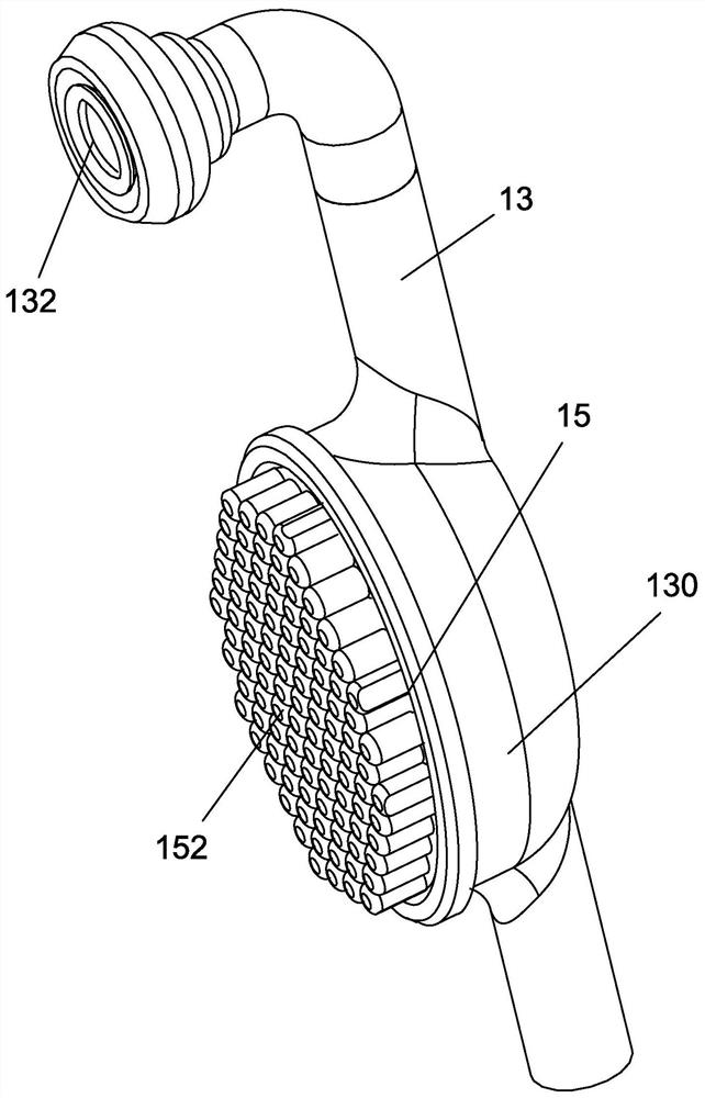
[0027] refer to Figure 1 to Figure 4 ,Such as Figure 1 to Figure 4 A pulsating induction soap dispenser shown includes a housing 10, the housing 10 is provided with a detachable soap storage part 11, and the housing 10 is provided with a soap dispenser for extracting from the soap storage part 11. A soap liquid pump 12 for soap liquid, the housing 10 is also provided with a battery compartment 101 for storing batteries (not shown), an inductive transmitter 102 and an inductive receiver 103, and the housing 10 is provided with The circuit board 104 connected to the battery, the inductive transmitter 102, the inductive receiver 103 and the soap pump 12, the top of the ho...


PUM


Abstract

The invention provides a pulsation type induction soap dispenser which comprises a shell, the shell is provided with a soap storage part, a soap pump is arranged in the shell, a battery bin, an induction emitter and an induction receiver are further arranged on the shell, a circuit board is arranged in the shell, a starting switch is arranged at the top of the shell, and a soap liquid flow channelis formed in the shell. A liquid outlet of the soap liquid pump is connected with the soap liquid flow channel, a silica gel membrane is arranged at an outlet of the soap liquid flow channel, and a slit is formed in the silica gel membrane; an elastic volume expansion device is arranged at the position, located on the upstream of the silica gel membrane, of the soap liquid flow channel; and the expansion volume of an elastic volume expansion device is smaller than the volume of liquid output by the soap pump liquid at a single liquid pumping beat. The soap dispenser has the advantages that residual liquid soap is not easy to remain at the liquid soap outlet, and soap liquid caking is avoided or reduced.

Description

technical field [0001] The invention relates to the field of soap dispensers, in particular to a pulsating induction soap dispenser. Background technique [0002] The induction soap dispenser generally senses the position of the human hand through the induction transmitter and the induction receiver, so as to control the driving of the soap pump to provide soap for the user. However, the existing induction soap dispenser is generally simple because of the soap outlet. Pipeline type, it is easy to leave part of the soap liquid in the soap liquid outlet after the soap liquid output is completed, it is easy to cause the soap liquid water to evaporate and agglomerate and adhere to the inner wall of the soap liquid outlet, causing the blockage of the soap liquid outlet and seriously affecting the soap liquid The extrusion flow rate is also high, and the agglomerated soap block on the inner wall of the soap liquid outlet is also prone to rush out of the soap liquid outlet along wi...

Claims


Application Information

Patent Timeline
Patent Type & Authority Applications(China)
IPC IPC(8): A47K5/12
CPCA47K5/12A47K5/1211
Inventor 李作明唐伟朱灿锋钱和胜
Owner 제지앙인터하사인텔리전트테크놀로지컴퍼니리미티드
Learn More