


Quick Research
Generate reliable direction feasibility study reports for your R&D in just a few steps.

Technical Q&A
Discover and master advanced knowledge NOW. Basics, ideas, possibilities, all at once.

Find Solutions
As an expert in R&D theories, this can generate solutions to your technical problems instantly.

Evaluate Feasibility
Analyze your overall solution with one click, know your potential R&D risks in advance.

Monitor Landscape
Get weekly tech updates, stay abreast of the latest tech innovations and key insights.
Camera lens group
A camera lens and lens technology, applied in the field of camera lens sets, can solve the problems of high sensitivity, and the processing and assembling ability cannot meet the needs of mass production, and achieve the effect of optimizing optical parameters and good imaging quality.
- Summary
- Abstract
- Description
- Claims
- Application Information
AI Technical Summary
Problems solved by technology
Method used
Image

Examples
Embodiment 1
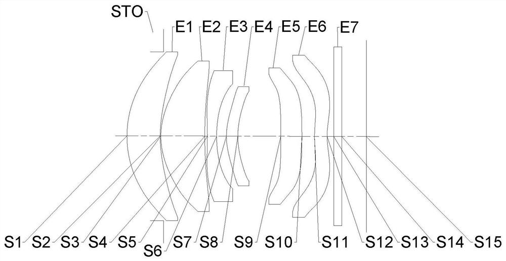
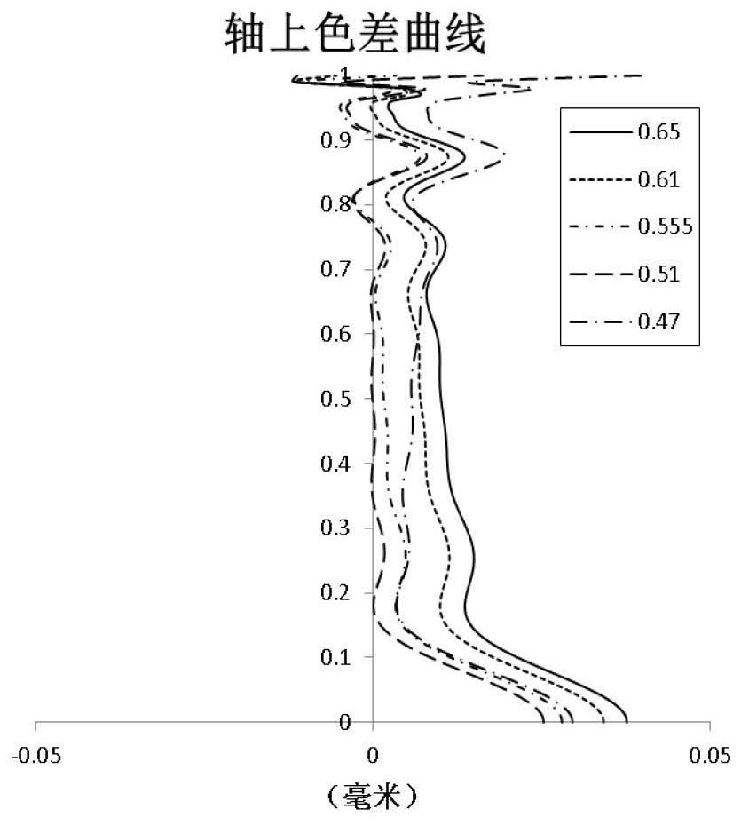
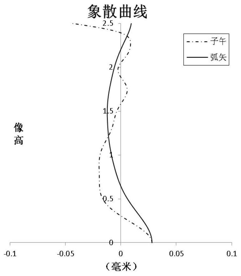
[0062] Refer to the following Figure 1 to Figure 2D An imaging lens group according to Embodiment 1 of the present application will be described. figure 1 A schematic structural diagram of the camera lens group according to Embodiment 1 of the present application is shown.
[0063] like figure 1 As shown, the camera lens group includes in sequence from the object side to the image side: a diaphragm STO, a first lens E1, a second lens E2, a third lens E3, a fourth lens E4, a fifth lens E5, a sixth lens E6, Filter E7 and imaging surface S15.
[0064] The first lens E1 has positive refractive power, its object side S1 is convex, and its image side S2 is concave. The second lens E2 has positive refractive power, its object side S3 is convex, and its image side S4 is concave. The third lens E3 has negative refractive power, its object side S5 is concave, and its image side S6 is concave. The fourth lens E4 has positive refractive power, its object side S7 is convex, and its i...
Embodiment 2
[0079] Refer to the following Figure 3 to Figure 4D An imaging lens group according to Embodiment 2 of the present application will be described. In this embodiment and the following embodiments, for the sake of brevity, descriptions similar to those in Embodiment 1 will be omitted. image 3 A schematic structural diagram of the camera lens group according to Embodiment 2 of the present application is shown.
[0080] like image 3 As shown, the camera lens group includes in sequence from the object side to the image side: a diaphragm STO, a first lens E1, a second lens E2, a third lens E3, a fourth lens E4, a fifth lens E5, a sixth lens E6, Filter E7 and imaging surface S15.
[0081] The first lens E1 has positive refractive power, its object side S1 is convex, and its image side S2 is concave. The second lens E2 has positive refractive power, its object side S3 is convex, and its image side S4 is concave. The third lens E3 has negative refractive power, its object side ...
Embodiment 3
[0093] Refer to the following Figure 5 to Figure 6D An imaging lens group according to Embodiment 3 of the present application is described. Figure 5 A schematic structural diagram of a camera lens group according to Embodiment 3 of the present application is shown.
[0094] like Figure 5 As shown, the camera lens group includes in sequence from the object side to the image side: a diaphragm STO, a first lens E1, a second lens E2, a third lens E3, a fourth lens E4, a fifth lens E5, a sixth lens E6, Filter E7 and imaging surface S15.
[0095] The first lens E1 has positive refractive power, its object side S1 is convex, and its image side S2 is concave. The second lens E2 has positive refractive power, its object side S3 is convex, and its image side S4 is concave. The third lens E3 has negative refractive power, its object side S5 is concave, and its image side S6 is concave. The fourth lens E4 has positive refractive power, its object side S7 is convex, and its image ...
PUM
 Abstract
Description
Claims
Application Information
 - R&D Engineer
- R&D Manager
- IP Professional
- Industry Leading Data Capabilities
- Powerful AI technology
- Patent DNA Extraction
Browse by: Latest US Patents, China's latest patents, Technical Efficacy Thesaurus, Application Domain, Technology Topic, Popular Technical Reports.
© 2024 PatSnap. All rights reserved.Legal|Privacy policy|Modern Slavery Act Transparency Statement|Sitemap|About US| Contact US: help@patsnap.com