
High-efficiency parallel axis heightened input speed reducer

A parallel axis, high-efficiency technology, applied in transmission parts, gear transmissions, belts/chains/gears, etc., can solve the problems of reduced power generation efficiency, reduced angle, single product specifications, etc., to increase power generation and improve utilization. rate, the effect of increasing optionality

Pending Publication Date: 2020-10-30
JIANGYIN SUNSLEW MACHINERY EQUIP
View PDF0 Cites 3 Cited by
  • Summary
  • Abstract
  • Description
  • Claims
  • Application Information

AI Technical Summary

Problems solved by technology

[0002] The center distance between the input shaft and the output shaft of the existing parallel shaft rotary reducer is relatively small. When solving the problem of tracking the sun by the photovoltaic panel on the bracket, it is necessary to consider that the photovoltaic panel may collide with the input shaft during tracking, so the rotary reducer is hard There is a very high requirement for the limit, which leads to the limitation of the tracking angle of the entire photovoltaic panel. If the angle is reduced, the power generation efficiency will be reduced; at the same time, due to the small center distance between the input shaft and the output shaft, it can meet There may be no place for the motor required by the working conditions, which increases the difficulty of motor selection; and the existing parallel shaft rotary reducer is suitable for a single product specification, which cannot meet the needs of product diversification

Method used


Image

  • High-efficiency parallel axis heightened input speed reducer
  • High-efficiency parallel axis heightened input speed reducer
  • High-efficiency parallel axis heightened input speed reducer

Examples


Embodiment Construction

[0017] The present invention is described in further detail now in conjunction with accompanying drawing. The drawings are all simplified schematic diagrams, which only illustrate the basic structure of the present invention in a schematic manner, so they only show the configurations related to the present invention.

[0018] In the description of the invention, it should be noted that the terms "upper", "lower", "inner", "outer", "front end", "rear end", "both ends", "one end", "another end" etc. The indicated orientation or positional relationship is based on the orientation or positional relationship shown in the drawings, and is only for the convenience of describing the present invention and simplifying the description, rather than indicating or implying that the referred device or element must have a specific orientation, or in a specific orientation. construction and operation, therefore, should not be construed as limiting the invention.

[0019] In the description of...


PUM


Abstract

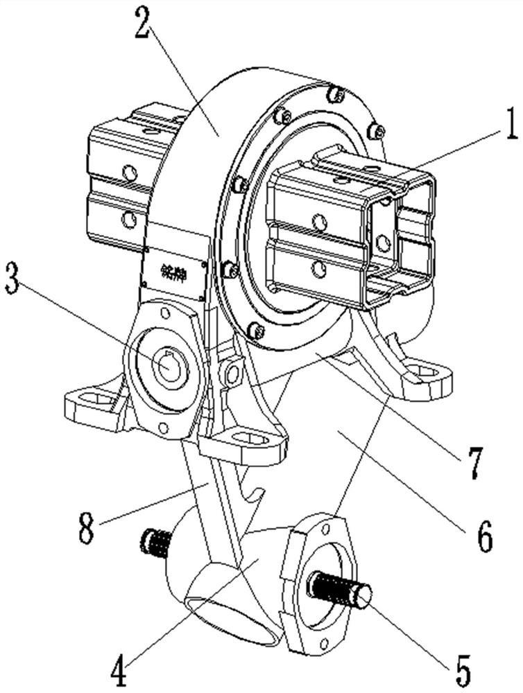
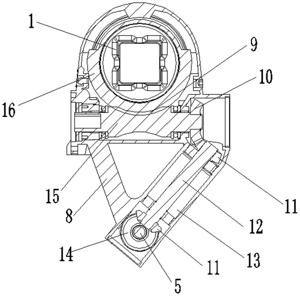
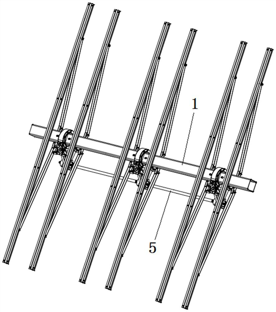
The invention discloses a high-efficiency parallel axis heightened input speed reducer which is divided into an upper base body and a lower base body. The upper base body comprises a worm wheel cavity, a first worm cavity and an output shaft. A worm wheel is arranged in the worm wheel cavity. A first worm is arranged in the first worm cavity. The first worm is engaged with the worm wheel. The output shaft sequentially penetrates through the worm wheel cavity and the worm wheel. The lower base body comprises a gear cavity, a second worm cavity and a connecting rod shaft. A first bevel gear is arranged in the gear cavity. The connecting rod shaft sequentially penetrates through the gear cavity and the first bevel gear. A second worm is arranged in the second worm cavity. The two ends of thesecond worm are sleeved with second bevel gears. The inner end of the first worm is sleeved with a third bevel gear. The second bevel gears are engaged with the first bevel gear and the third bevel gear separately. According to the high-efficiency parallel axis heightened input speed reducer, the center distance is increased when an input shaft and the output shaft are parallel to be used for solving the problem of photovoltaic panel angle restriction, and power generation efficiency is improved; and meanwhile, a motor can be connected into different input ends to reach the vertical or horizontal state of the input shaft and the output shaft to be adapted to product diversification.

Description

technical field [0001] The invention belongs to the field of solar tracking reducer, and relates to a high-efficiency parallel shaft heightened input reducer. Background technique [0002] The center distance between the input shaft and the output shaft of the existing parallel shaft rotary reducer is relatively small. When solving the problem of tracking the sun by the photovoltaic panel on the bracket, it is necessary to consider that the photovoltaic panel may collide with the input shaft during tracking, so the rotary reducer is hard There is a very high requirement for the limit, which leads to the limitation of the tracking angle of the entire photovoltaic panel. If the angle is reduced, the power generation efficiency will be reduced; at the same time, due to the small center distance between the input shaft and the output shaft, it can meet The motor required by the working conditions may have no place to install, which increases the difficulty of motor selection; an...

Claims


Application Information

Patent Timeline
Patent Type & Authority Applications(China)
IPC IPC(8): F16H1/22F16H57/023F16H57/038F16H57/039
CPCF16H1/225F16H57/023F16H57/038F16H57/039F16H2057/02034F16H2057/02069
Inventor 华伟黄相林陈黔宁陈凯
Owner JIANGYIN SUNSLEW MACHINERY EQUIP
Learn More