Dual-motor series-parallel hybrid power device and vehicle
A hybrid and hybrid technology, which is applied to the arrangement of multiple prime movers of power devices, pneumatic power devices, and general power devices, can solve the problems of high requirements and high costs, and achieve low manufacturing difficulty and low cost. The effect of low cost, great economic benefit and social benefit
- Summary
- Abstract
- Description
- Claims
- Application Information
AI Technical Summary
Problems solved by technology
Method used
Image
Examples
Embodiment 1
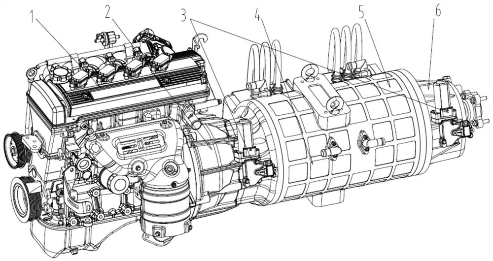
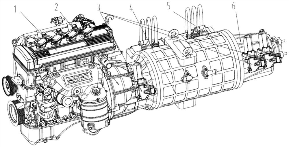
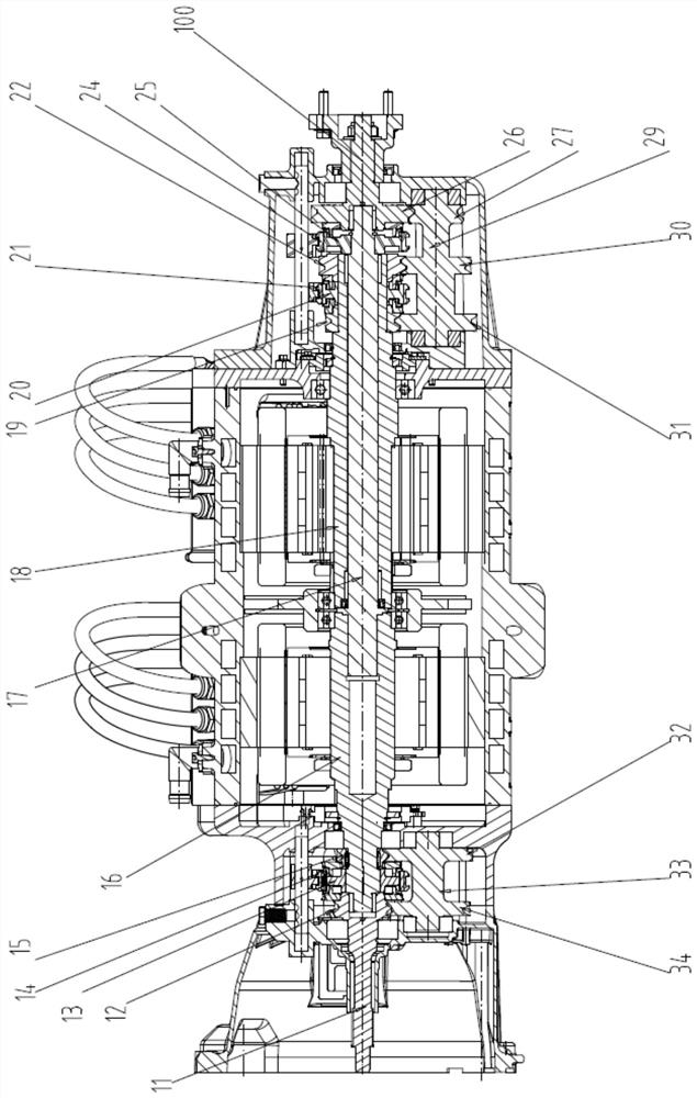
[0025] Such as Figure 1 to Figure 3 As shown, a dual-motor series hybrid device in this embodiment includes a front transmission 2, a generator 4, a driving motor 5 and a rear transmission 6, the generator 4 and the driving motor 5 are integrated and located in the front transmission 2 and the rear derailleur, the rear derailleur 6 is located at the drive motor 5 side. In this embodiment, the engine 1 transmits power to the front transmission 2 through the input shaft 11. The front transmission 2 is a three-shaft two-speed transmission, which is a common transmission in the prior art and has a direct gear and an overdrive gear. Use overdrive gear when running at low speed, so that you can increase the speed of the generator, thereby improving power generation efficiency; use direct gear when the engine is running at high speed, so that you can avoid damage to the generator caused by overspeed running. In addition, the front derailleur can also form a combined transmission wi...
Embodiment 2
[0032] Such as figure 1 and as Figure 4 As shown, the difference between this embodiment and the above-mentioned embodiment is that the pure electric direct drive and pure oil two-gear structure of this embodiment, the driving motor 5 is a single-stage drive, and the pure oil drive or parallel hybrid of the rear transmission 6 has high-grade and low-gear two files. The driving gear 19C of the driving motor 5 is set on the motor shaft 18, the constant mesh output driving gear 27 of the rear derailleur 6, the low gear driven gear 29 of the rear derailleur 6, the driven gear 31C of the driving motor 5 and the intermediate shaft of the rear derailleur 6 28 is integrally arranged; the low-gear active gear 23 of the rear derailleur 6, the rear gear shift gear hub 25 of the rear derailleur 6 are set on the input shaft 18, and the rear gear shift gear sleeve 24 of the rear derailleur 6 is set on the shift gear hub 25 . The high and low gears of the rear derailleur 6 can be switche...
Embodiment 3
[0034] Such as figure 1 with Figure 5 As shown, the difference between this embodiment and the above-mentioned embodiments is that this embodiment has a pure electric two-gear and pure oil two-gear structure, the drive motor 5 has two high-gear and low-gear, pure oil drive and parallel hybrid rear transmission 6 There are two gears, high and low.
[0035] In this embodiment, the low gear active gear 19 of the driving motor and the high gear active gear 22 of the driving motor are arranged on both sides of the high and low gear gear hub 20 of the driving motor, and the high and low gear gear sleeve 21 of the driving motor is set on the high and low gear gear hub 20. On the gear hub 20; the rear gear shift gear sleeve 24 of the rear derailleur is sleeved on the rear gear shift gear hub 25, and the constant mesh output driven gear 26 of the rear derailleur and the low gear driving gear 23 of the rear derailleur are located on the rear gear shift gear On both sides of the hub 2...
PUM
 Abstract
Description
Claims
Application Information
 - R&D
- Intellectual Property
- Life Sciences
- Materials
- Tech Scout
- Unparalleled Data Quality
- Higher Quality Content
- 60% Fewer Hallucinations
Browse by: Latest US Patents, China's latest patents, Technical Efficacy Thesaurus, Application Domain, Technology Topic, Popular Technical Reports.
© 2025 PatSnap. All rights reserved.Legal|Privacy policy|Modern Slavery Act Transparency Statement|Sitemap|About US| Contact US: help@patsnap.com


