
Fan bone side processing device

A processing device and fan bone technology, which is applied in metal processing, wood processing appliances, manufacturing tools, etc., can solve the problem of long-term holding of cutting knives and other problems, and achieve the effect of simple and simple structure, labor-saving and practicality

Active Publication Date: 2021-12-03
过丽清
View PDF0 Cites 0 Cited by
  • Summary
  • Abstract
  • Description
  • Claims
  • Application Information

AI Technical Summary

Problems solved by technology

This method has a drawback: it is very laborious to hold the cutter for a long time

Method used


Image

  • Fan bone side processing device
  • Fan bone side processing device
  • Fan bone side processing device

Examples


Embodiment Construction

[0022] The following are specific embodiments of the invention and in conjunction with the accompanying drawings, the technical solutions of the present invention are further described, but the present invention is not limited to these embodiments.

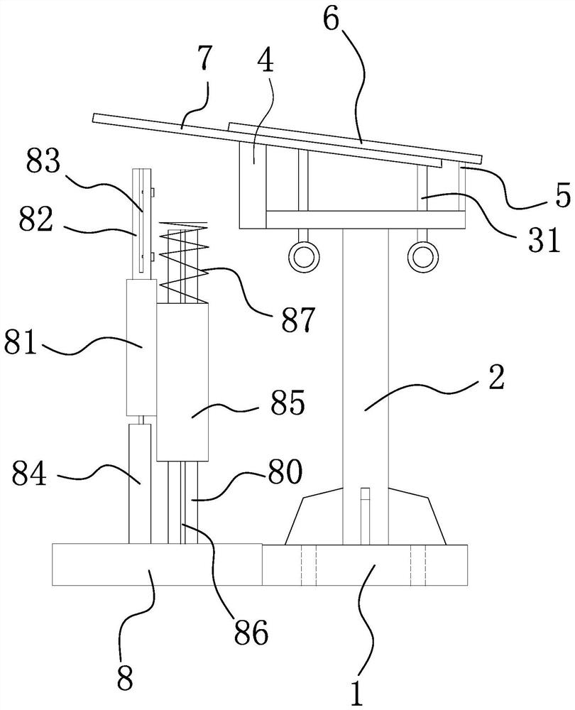
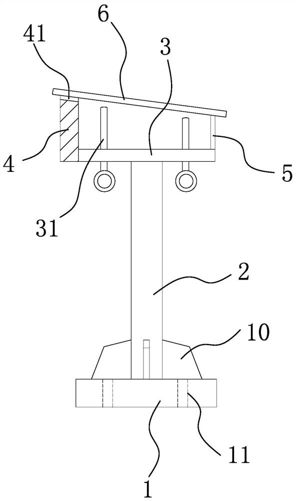
[0023] Such as figure 1 As shown, the fan bone side edge processing device includes a base 1, and the base 1 is block-shaped.

[0024] There is a column 2 on the base 1, a column hole is provided on the upper surface of the base 1, the lower end of the column is inserted into the column hole and the two are connected by welding, and a flat plate 3 is provided on the top of the column 2, and the flat plate 3 and the column 2 pass through Solder connection.

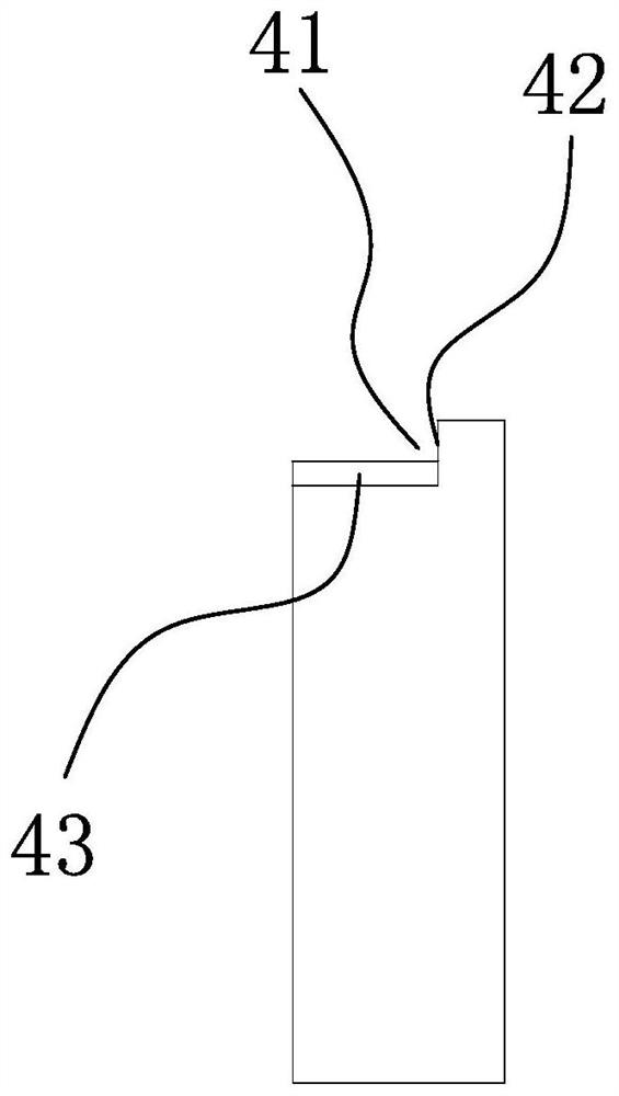
[0025] Such as Figure 1-4 As shown, one end of the flat plate 3 is provided with a vertical plate one 4, the flat plate 3 and the vertical plate one 4 are connected by welding, the other end of the flat plate 3 is provided with a vertical plate two 5, the vertical plate two ...


PUM


Abstract

The fan frame side processing device includes a base, a column is arranged on the base, a plate is arranged on the top of the column, a vertical plate is provided at one end of the flat plate, a vertical plate is provided at the other end of the flat plate, and the height of the vertical plate is Higher than the height of the vertical plate 2, it also includes an inclined pressure plate, the upper surface of the inclined pressure plate is fixed on the top of the vertical plate 1, the lower surface of the lower end of the inclined pressure plate is fixed on the top of the vertical plate 2, and a positioning is provided on the top side of the vertical plate 1. Notch, the cutting knife is placed in the positioning notch and the knife back of the cutting knife leans against the vertical surface of the positioning notch, and the flat plate is perforated with several screw rods that are threadedly connected with the flat plate and the upper end leans against the lower surface of the cutting knife.

Description

technical field [0001] The invention belongs to the technical field of fan processing, and in particular relates to a fan rib side processing device. Background technique [0002] The structure of the fan includes fan bones and fan paper. [0003] The fan bone includes two large side bones and a small bone in the middle. [0004] After the rough material of the large side bone is cut, when it needs to be processed such as removing the edges and corners, at present, the fixed side of the large side bone is processed by manually holding the cutter. This method has a drawback: it is very laborious to hold the cutter for a long time. Contents of the invention [0005] The object of the present invention is to address the above problems and provide a fan bone side edge processing device that can solve the above technical problems. [0006] To achieve the above object, the present invention adopts the following technical solutions: [0007] The fan frame side processing devi...

Claims


Application Information

Patent Timeline
Patent Type & Authority Patents(China)
IPC IPC(8): B27C5/00B27M3/24B26D1/02
CPCB26D1/02B27C5/00B27M3/24
Inventor 过丽清
Owner 过丽清
Learn More