
Locking device and tire burst safety emergency device

A locking device and locking block technology, applied in the field of vehicles, can solve problems such as tire damage, personnel and property losses, cumbersome and time-consuming operations, and achieve the effects of convenient operation and improved quality and efficiency

Pending Publication Date: 2020-10-27
山东泰斯福德科技发展有限公司
View PDF0 Cites 0 Cited by
  • Summary
  • Abstract
  • Description
  • Claims
  • Application Information

AI Technical Summary

Problems solved by technology

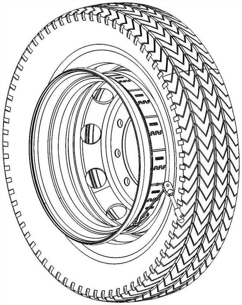
[0003] like figure 1 As shown, the emergency safety device for tire blowout in the integrated rim is locked circumferentially through the threaded assembly (screw and nut combination) at the connection. Due to the limitation of the working principle, it is necessary to use a tire pressure device to flatten the tire during locking to free up the tire. Wrench operation space, it is obvious that the operation of this locking method is cumbersome and time-consuming, and special tools are needed to press the tire crown to severe deformation
[0004] In addition, nowadays, off-road vehicles and light trucks with relatively large displacement often use split rims. These models often drive on highways and bear the risk of tire blowouts causing heavy losses to personnel and property.
At present, some military and special police vehicles in our country also use split rims, and the inside of the crown of the tire is reinforced with steel plates. If the crown is deformed, it will cause irreversible damage to the tire.

Method used


Image

  • Locking device and tire burst safety emergency device
  • Locking device and tire burst safety emergency device
  • Locking device and tire burst safety emergency device

Examples


Embodiment Construction

[0035] The application will be further described in detail below in conjunction with the accompanying drawings and embodiments. It should be understood that the specific embodiments described here are only used to explain related inventions, rather than to limit the invention. It should also be noted that, for ease of description, only parts related to the invention are shown in the drawings.

[0036] It should be noted that, in the case of no conflict, the embodiments in the present application and the features in the embodiments can be combined with each other. The present application will be described in detail below with reference to the accompanying drawings and embodiments.

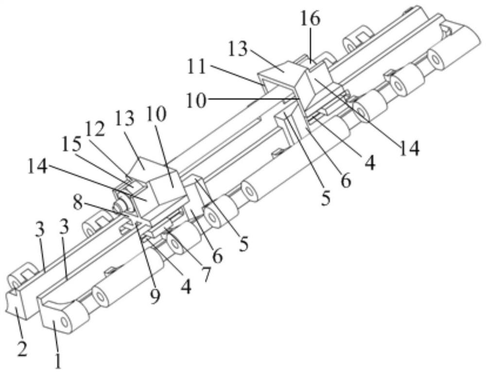
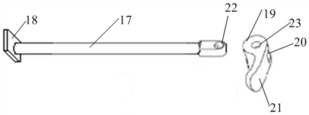
[0037] Such as figure 2 As shown, the locking device provided by the embodiment of the present invention includes: a first connecting piece 1 and a second connecting piece 2, the first connecting piece 1 and the second connecting piece 2 respectively include a connecting plate 3, and two connecti...


PUM


Abstract

The invention discloses a locking device and a tire burst safety emergency device. The locking device comprises a first connecting piece and a second connecting piece. Each of the first connecting piece and the second connecting piece comprises a connecting plate, and the two connecting plates are parallel and oppositely arranged; pressure bearing blocks are arranged on the connecting plates, andtwo locking blocks used for holding and loosening the pressure bearing blocks are connected between the two connecting plates in a sliding mode. And in a length direction of each connecting plate, thetwo locking blocks are connected through a connecting fastener. The tire burst safety emergency device comprises a supporting ring, the supporting ring comprises a plurality of supporting pieces, every two adjacent supporting pieces are movably connected, and the two ends of the supporting ring are connected through the locking device. In the invention, the two locking blocks tightly hold the pressure bearing blocks through the connecting fasteners, axial locking in the length direction of the connecting plates is converted into opposite movement between the two connecting plates, then circumferential locking of the tire burst emergency safety device is achieved, a crown does not need to be flattened, operation is convenient, and the quality and efficiency of installation of the tire burst emergency safety device are improved.

Description

technical field [0001] The present application generally relates to the field of vehicles, and in particular to a locking device and a tire burst safety emergency device. Background technique [0002] When the vehicle is in use, it may cause a tire blowout when the vehicle is out of air or damaged. Once the tire blows out, the tire may slip out of the rim, causing the vehicle to shift and roll over, causing danger. For this reason, a variety of tire burst emergency safety devices have appeared in the art, which are arranged on the surface of the rim, and can effectively support the rim without contacting the ground after the vehicle punctures, relying on the flat tire to continue driving for a certain distance, and keep the vehicle as safe as possible. . Wherein, the rim includes a one-piece rim and a split-type rim, the one-piece rim has a wheel groove, and compared with the common one-piece rim, the split-type rim has no wheel groove structure. [0003] Such as figure 1...

Claims


Application Information

Patent Timeline
Patent Type & Authority Applications(China)
IPC IPC(8): B60C17/00
CPCB60C17/00
Inventor 王忠
Owner 山东泰斯福德科技发展有限公司
Learn More