Condensing device for cooking equipment and cooking equipment
A technology of a condensation device and cooking equipment, which is applied to the structure of cooking utensils, steam cooking utensils, lighting and heating equipment, etc., can solve the problems of large space occupation and poor condensation effect, and achieve easy collection, rapid condensation, and continuous condensation. Good results
- Summary
- Abstract
- Description
- Claims
- Application Information
AI Technical Summary
Problems solved by technology
Method used
Image
Examples
Embodiment 1
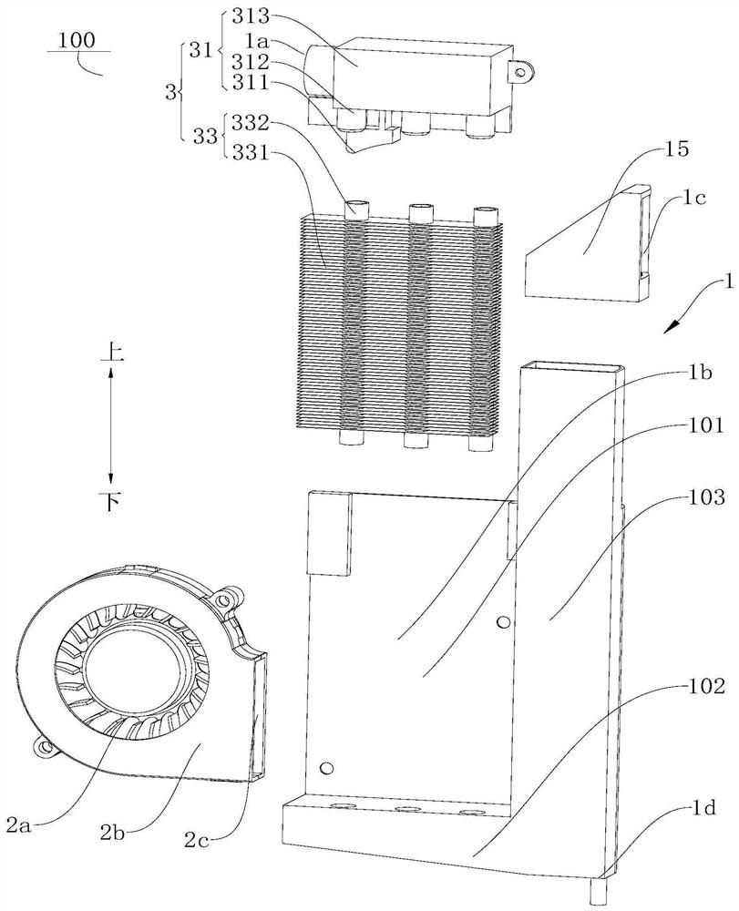
[0095] A condensing device 100, such as figure 1 As shown, it includes: a steam distribution shell 1, a fan 2a and a steam condensing assembly 3.
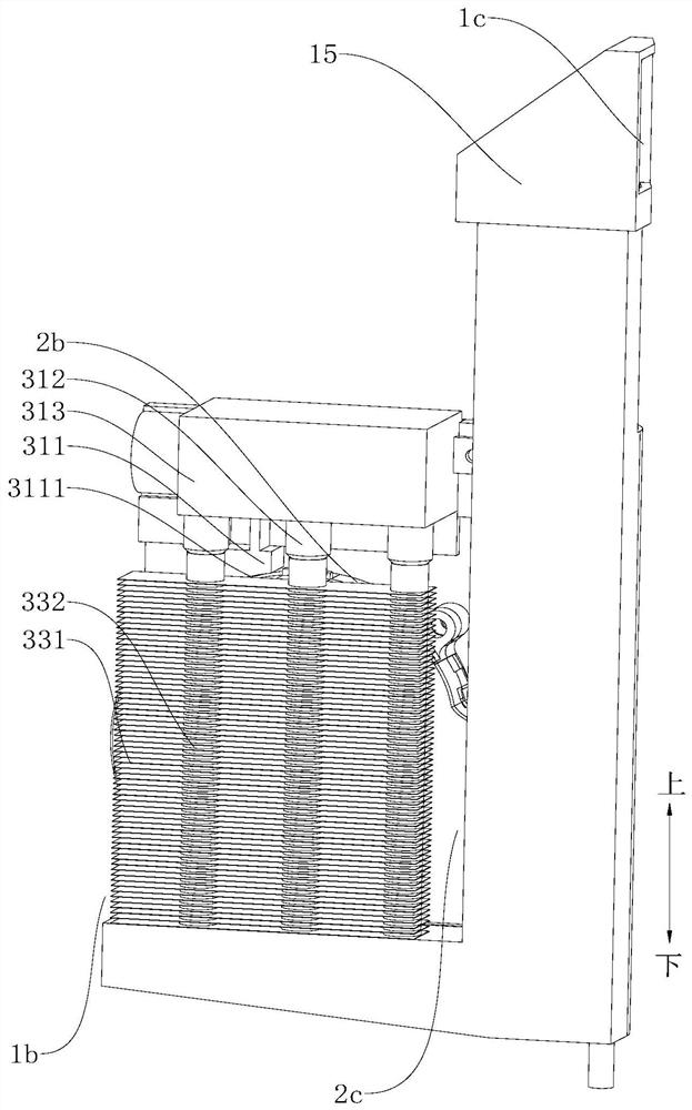
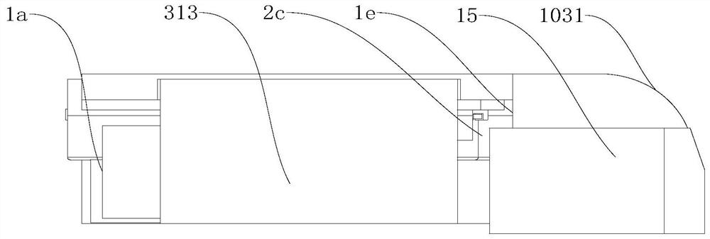
[0096] Among them, such as figure 1 and Figure 6 As shown, an air passage chamber 101 , an exhaust chamber 103 and a drainage chamber 102 are formed in the steam distribution housing 1 . Such as figure 1 As shown, the steam distribution shell 1 is provided with a second air inlet 1b, an air exhaust port 1e and a mixed air exhaust port 1c, the exhaust chamber 103 is provided with a mixed air exhaust port 1c, the exhaust chamber 103 and the The air chambers 101 communicate with each other through the air outlet 1e. . Such as figure 1 and figure 2 As shown, the steam condensing assembly 3 is detachably connected in the air passage chamber 101, the first air inlet 1a is formed on the steam condensing assembly 3 to let in high-temperature steam, the outlet of the steam condensing assembly 3 communicates with the drain chamber 1...
Embodiment 2
[0099] A condensing device 100, such as figure 1 As shown, it includes: a steam distribution shell 1, a fan 2a and a steam condensing assembly 3.
[0100] Different from Example 1, as Figure 5 and Figure 6 As shown, the steam distribution housing 1 includes: a first mounting plate 11 , a plurality of second mounting plates 12 and a plurality of third mounting plates 13 . Among them, such as Figure 6 As shown, a plurality of second mounting plates 12 are connected to the bottom of the first mounting plate 11 , and the plurality of second mounting plates 12 enclose to form a drainage chamber 102 . Such as Figure 6 As shown, a plurality of third mounting plates 13 are connected between the first mounting plate 11 and the second mounting plate 12, and the plurality of third mounting plates 13 surround and form an exhaust chamber 103, and the exhaust chamber 103 communicates with the drainage chamber 102 With the wind chamber 101 and the exhaust chamber 103, an air outlet ...
Embodiment 3
[0103] A condensing device 100, such as figure 1As shown, it includes: a steam distribution shell 1, a fan 2a and a steam condensing assembly 3.
[0104] The difference from Example 2 is that, as Figure 6 and Figure 7 As shown, the wall surface of the exhaust chamber 103 facing the air outlet 1e forms an arc surface 1031 . Such as figure 1 As shown, the top of the exhaust chamber 103 is detachably connected with an exhaust head 15, such as Figure 4 As shown, one side of the exhaust head 15 forms the mixed air exhaust port 1c, and the top of the exhaust head 15 is inclined downward toward the direction away from the mixed air exhaust port 1c. Fan 2a is a diagonal flow fan.
[0105] A cooking device 1000, such as Figure 10 As shown, it includes a machine body 200 and a condensing device 100 . The difference from the second embodiment is that the condensing device 100 is the condensing device 100 described in the third embodiment.
PUM
 Abstract
Description
Claims
Application Information
 - Generate Ideas
- Intellectual Property
- Life Sciences
- Materials
- Tech Scout
- Unparalleled Data Quality
- Higher Quality Content
- 60% Fewer Hallucinations
Browse by: Latest US Patents, China's latest patents, Technical Efficacy Thesaurus, Application Domain, Technology Topic, Popular Technical Reports.
© 2025 PatSnap. All rights reserved.Legal|Privacy policy|Modern Slavery Act Transparency Statement|Sitemap|About US| Contact US: help@patsnap.com


