
Multibeam scanning apparatus

A scanning device and multi-beam technology, applied in the field of printers, can solve the problems of complex structure and large volume of color printers

Inactive Publication Date: 2003-08-13
SAMSUNG ELECTRONICS CO LTD
View PDF0 Cites 2 Cited by
  • Summary
  • Abstract
  • Description
  • Claims
  • Application Information

AI Technical Summary

Problems solved by technology

[0006] In a color printer, it is necessary to set up a separate light beam scanning device corresponding to each specific color. Therefore, the color printer has a complex structure and a large volume.

Method used


Image

  • Multibeam scanning apparatus
  • Multibeam scanning apparatus
  • Multibeam scanning apparatus

Examples


Embodiment Construction

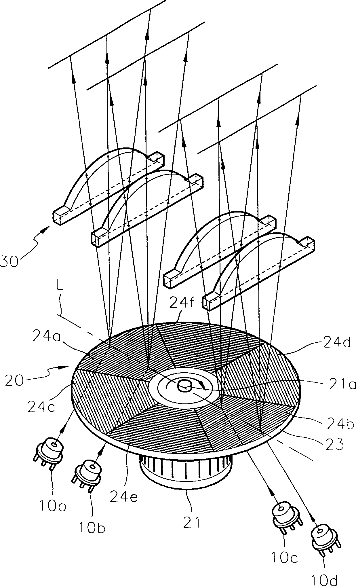
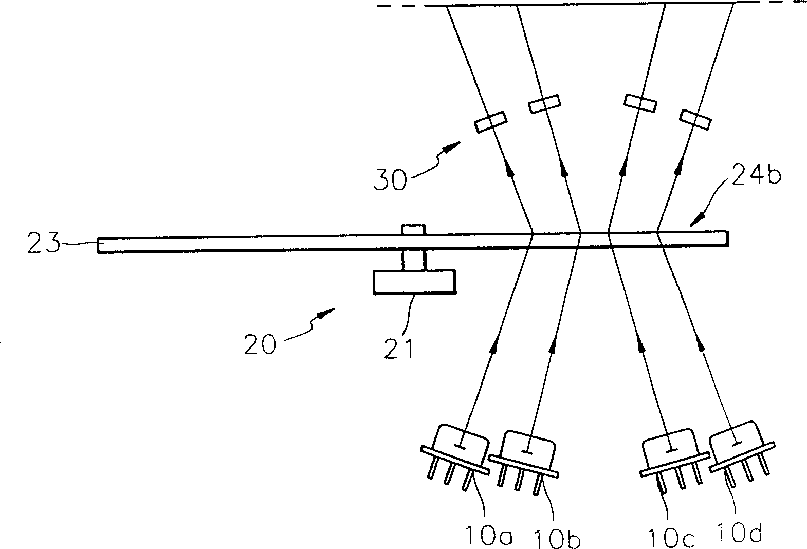
[0018] see figure 2 , the multi-beam scanning device according to the first embodiment of the present invention includes at least two light sources 10a, 10b, 10c and 10d for generating and emitting light, and one for deflecting and projecting light emitted from the light sources 10a, 10b, 10c and 10d a beam deflector 20 for the beam, and a beam corrector 30 for correcting the deflected beam.

[0019] The light sources 10a to 10d are semiconductor laser emitters, and can be selectively driven.

[0020] The beam deflector 20 includes a drive motor 21 and a deflection plate 23, the deflection plate 23 is mounted on the rotation shaft 21a of the drive motor 21, and has a plurality of areas 24a to 24f.

[0021] The deflection disk 23 is equally divided into regions 24a to 24f. The shaped regions 24 a to 24 f diffract and transmit the incident beam to deflect and project the diffracted beam by a unit of a scanning line based on the rotation of the deflection disk 23 .

[0022] T...


PUM


Abstract

A multi-beam scanning apparatus including at least two optical sources; a beam deflector including a deflection disc having a plurality of sectors for diffracting and transmitting incident beams, and a driving source for rotating the deflection disc, for deflecting and projecting beams emitted from the optical source; and a beam correcting means installed on a light path, for correcting the beams deflected by the beam deflector.

Description

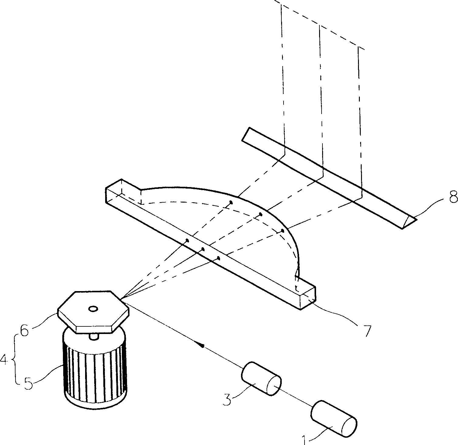
technical field [0001] The present invention relates to a printer, and more particularly to a multi-beam scanning device for simultaneously deflecting and scanning at least two beams emitted from a light source to form an electrostatic latent image on a photoreceptor. Background technique [0002] Conventional beam scanning devices used in printers charge the photoreceptor by main scanning of the beam deflector and subscanning of the movement or rotation of the photoreceptor. [0003] figure 1 shows the optical layout of a conventional beam scanning device comprising a light source 1 for emitting light, a beam deflector 4 for deflecting the beam from the light source 1, and a beam deflector for correcting the beam 4 Deviated f-theta lens 7 for deflected light. [0004] In addition, a focusing lens 3 is disposed between the light source 1 and the beam deflector 4 to focus the diverging light beam from the light source 1 . The beam deflected by the beam deflector 4 is refle...

Claims


Application Information

Patent Timeline
Patent Type & Authority Patents(China)
IPC IPC(8): B41J2/44B41J2/385G02B26/10H04N1/191H04N1/50
CPCH04N1/1265G02B26/106H04N1/506H04N1/1912B41J2/385
Inventor 严在鎔李源馨韩哲暎加里·H·康纳斯
Owner SAMSUNG ELECTRONICS CO LTD
Learn More