
A cable tray

A technology of cable bridge and main bridge, which is applied in the field of cable bridge, and can solve the problems of inconvenient adjustment of spacing, poor practicability, and affecting maintenance efficiency, etc.

Active Publication Date: 2021-09-21
天津龙鼎熙石化新能源科技有限公司
View PDF10 Cites 0 Cited by
  • Summary
  • Abstract
  • Description
  • Claims
  • Application Information

AI Technical Summary

Problems solved by technology

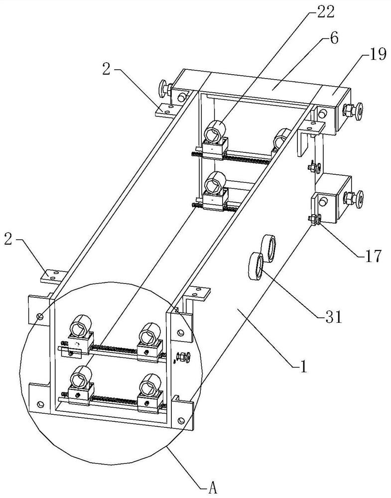
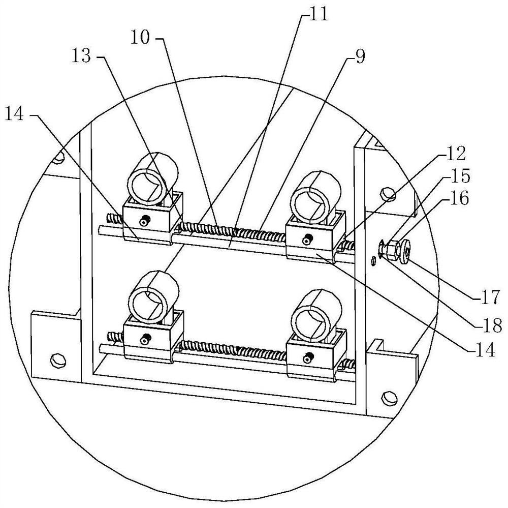
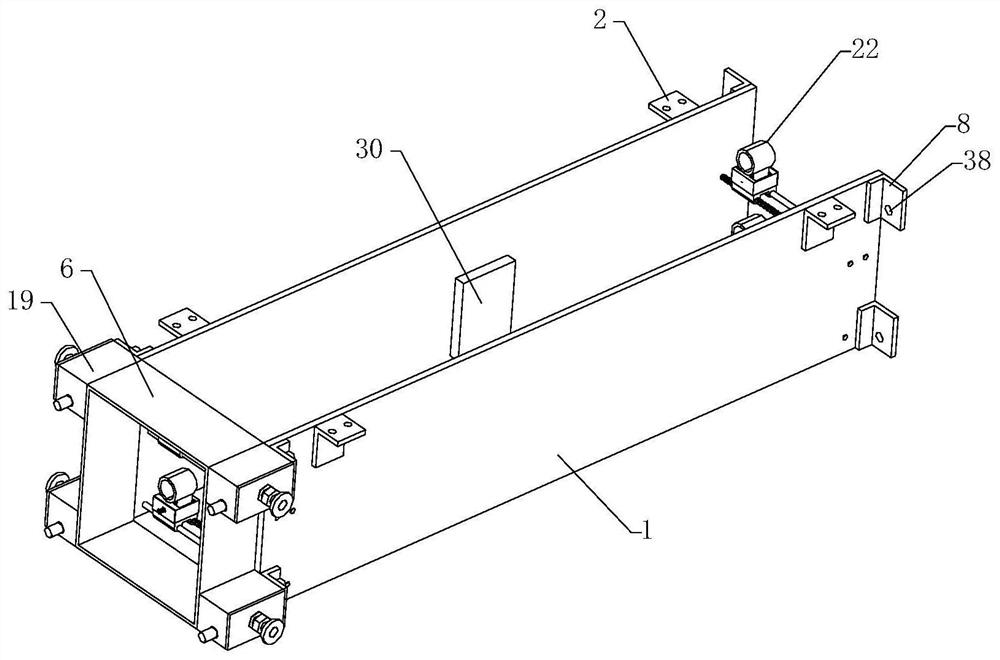
[0002] With the rapid development of people's living standards, more and more cable trays are installed in buildings. The main function of cable trays is to connect and route cables to facilitate the routing of electrical devices in buildings. It reduces the occupied space of the cables, and is convenient for people to overlap and manage the cables. The cable tray can fix and protect the cables to a certain extent. Due to the construction of various projects in our country, it is necessary to use different Standard cables are used for power transmission or information transmission. The existing cable brackets need to place multiple different cables together. After fixing, the spacing cannot be adjusted conveniently. The practicability is poor, and when maintenance is performed later, The entire bridge needs to be dismantled, which requires a lot of labor and affects the efficiency of later maintenance. Therefore, we propose a cable bridge to solve the above-mentioned problems

Method used


Image

  • A cable tray
  • A cable tray
  • A cable tray

Examples


Embodiment Construction

[0025] In order to make the object, technical solution and advantages of the present invention clearer, the present invention will be further described in detail below in conjunction with the accompanying drawings and embodiments. It should be understood that the specific embodiments described here are only used to explain the present invention, not to limit the present invention.

[0026] In the description of the present invention, it should be noted that the terms "center", "upper", "lower", "left", "right", "front", "rear", "vertical", "horizontal", The orientation or positional relationship indicated by "inner", "outer", etc. is based on the orientation or positional relationship shown in the drawings, and is only for the convenience of describing the present invention and simplifying the description, rather than indicating or implying that the referred device or element must have Certain orientations, constructed and operative in certain orientations, therefore are not t...


PUM


Abstract

The present invention relates to the technical field of cable bridges, in particular to a cable bridge, comprising a main bridge, mounting plates are respectively arranged at the upper ends of both sides of the main bridge, an alarm mechanism is provided at the inner middle end of the main bridge, and the inner two ends of the main bridge are respectively A spacing adjustment mechanism is provided, and each spacing adjustment mechanism includes an adjustment assembly, and each adjustment assembly includes two moving plates that can move horizontally in opposite directions, and each moving plate is respectively provided with a cable clamping head, each of the main bridge The two ends are respectively provided with detachable connecting mechanisms, and each connecting mechanism includes a connecting frame that can be docked with the end of the main bridge frame and locking assemblies installed on the upper and lower ends of the two sides of the connecting frame respectively, and the two sides of the main bridge frame are respectively provided with The connection plate that can be detachably connected with each locking component can adjust the fixed cables to improve the practicality of installation, and can efficiently separate each hinge frame separately to improve the efficiency of later maintenance.

Description

technical field [0001] The invention relates to the technical field of cable bridges, in particular to a cable bridge. Background technique [0002] With the rapid development of people's living standards, more and more cable trays are installed in buildings. The main function of cable trays is to connect and route cables to facilitate the routing of electrical devices in buildings. It reduces the occupied space of the cables, and is convenient for people to overlap and manage the cables. The cable bridge can play a certain role in fixing and protecting the cables. Due to the construction of various projects in our country, it is necessary to use different Standard cables are used for power transmission or information transmission. The existing cable brackets need to place multiple different cables together. After fixing, the spacing cannot be adjusted conveniently. The practicability is poor, and when maintenance is performed later, The entire bridge needs to be removed, w...

Claims


Application Information

Patent Timeline
Patent Type & Authority Patents(China)
IPC IPC(8): H02G3/04H02G3/06G01K13/00G08B21/24
CPCG01K13/00G08B21/24H02G3/0406H02G3/06
Inventor 黎忠琴
Owner 天津龙鼎熙石化新能源科技有限公司
Learn More