
A soil detector

A detector and soil technology, applied in the field of soil detectors, can solve the problems of easy mixing of soil, inconvenience of deep soil sampling, affecting soil research and analysis work, etc.

Active Publication Date: 2021-04-23
安徽众大天人生态环境有限公司
View PDF12 Cites 2 Cited by
  • Summary
  • Abstract
  • Description
  • Claims
  • Application Information

AI Technical Summary

Problems solved by technology

[0005] The purpose of the present invention is to solve the problem that the existing design structure is simple, it is not convenient to sample the deep soil, and in the sampling process, the soil at each depth is easy to mix during the sampling process, which affects the soil research and analysis work. A deep soil collection device for environmental detection

Method used


Image

  • A soil detector
  • A soil detector
  • A soil detector

Examples


Embodiment 1

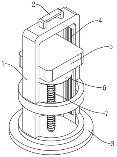
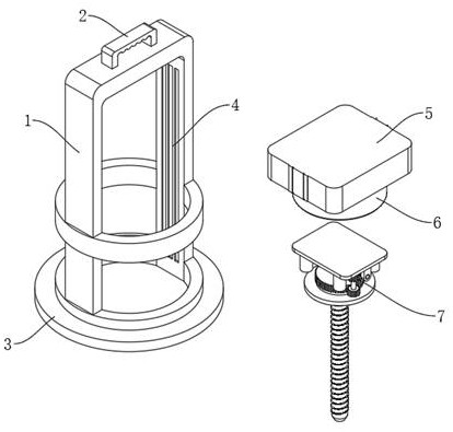
[0026] see Figure 1-4 , a soil detector, comprising a mounting frame 1, an auxiliary handle 2 and a fixed base 3, the auxiliary handle 2 is fixedly connected to the top of the mounting frame 1, the fixed base 3 is fixedly connected to the bottom end of the mounting frame 1, and the fixed base 3 An anti-slip protrusion is fixedly connected on the bottom surface of the mounting frame 1; a driving slide rail 4 is fixedly connected to the inner wall of the mounting frame 1, and a mounting shell 5 is arranged on the driving slide rail 4, and a connecting plate is fixedly connected to the side wall of the mounting shell 5. The installation housing 5 is slidably connected on the drive slide rail 4 through the connecting plate; the lower end surface of the installation housing 5 is fixedly connected with the installation cover 6, and the connection earth drilling device 7 is installed in the installation housing 5 and the installation cover 6, and the installation cover Soil sampling...

Embodiment 2

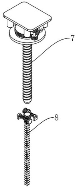
[0032] see Figure 5 The difference in the basis of Embodiment 1 is that the soil sampling detection device 8 includes a drive mechanism, the drive mechanism includes a servo motor 801, a second worm 802 and a connecting block 803, and the servo motor 801 is fixedly connected to the fixed cylinder 710 The bottom surface of the second worm 802 is fixedly connected with the output shaft of the servo motor 801, and the end of the second worm 802 away from the servo motor 801 is rotationally connected with the connecting block 803, and the connecting block 803 is fixedly connected on the inner bottom surface of the fixed cylinder 710, and the driving mechanism There are two groups, and the two groups of drive mechanisms are mounted symmetrically inside the fixed cylinder 710 .

[0033] The soil sampling detection device 8 also includes a sampling detection mechanism, the sampling detection mechanism includes a second worm wheel 804, the second worm wheel 804 is meshed with the sec...


PUM


Abstract

The invention discloses a soil detector, belonging to the technical field of soil detection equipment; a soil detector, comprising a mounting frame, an auxiliary handle and a fixed base, the auxiliary handle is fixedly connected to the top of the mounting frame, and the fixed base is fixedly connected to the The bottom of the mounting frame is fixedly connected with an anti-skid protrusion on the bottom surface of the fixed base; the inner wall of the mounting frame is fixedly connected with a driving slide rail, the driving slide rail is provided with a mounting shell, and the side wall of the mounting shell is fixedly connected with a The connecting plate, the mounting shell is slidably connected to the drive slide rail through the connecting plate; the mounting cover is fixedly connected to the lower surface of the mounting shell, the connecting earth drilling device is installed in the mounting shell and the mounting cover, and the mounting cover is also installed with Soil sampling and detection device; the present invention effectively solves the problem that the existing design structure is simple, it is inconvenient to sample the deep soil, and in the sampling process, the soil at various depths is easy to mix during the sampling process, which affects the soil research and analysis work.

Description

technical field [0001] The invention relates to the technical field of soil testing equipment, in particular to a soil testing instrument. Background technique [0002] Soil is a loose and porous substance that exists on the earth's land surface and can grow green plants. It is composed of various granular minerals, organic substances, water, air, microorganisms, etc. The physical and chemical properties of the soil change with the depth of the soil layer. changes; in soil science, agronomy, water conservancy, environmental testing and other fields, in order to better study environmental changes, it is often necessary to sample and study soil at various depths. For surface soil, only artificial It is enough to collect and detect with a simple method, but in order to better sample and detect deep soil soil, it is particularly important to design a soil detector that can collect deep soil conveniently and quickly. [0003] At present, the ordinary soil detectors that already ...

Claims


Application Information

Patent Timeline
Patent Type & Authority Patents(China)
IPC IPC(8): G01N1/08G01N33/24
CPCG01N1/08G01N33/24
Inventor 陈欣荣
Owner 安徽众大天人生态环境有限公司
Learn More