Furnace tube hoisting device

A hoisting device and furnace tube technology, applied in transportation and packaging, load hanging components, track systems, etc., can solve problems such as easy damage to the furnace tube and construction personnel at the bottom of the furnace, easy swing of the electric hoist, and easy slippage of short slings

Pending Publication Date: 2020-10-20
LIANHUA CONSTR GROUP XINJIANG
View PDF0 Cites 0 Cited by
  • Summary
  • Abstract
  • Description
  • Claims
  • Application Information

AI Technical Summary

Problems solved by technology

[0003] However, in the above process, the short sling is easy to slip, and there is a certain danger in the hoisting process. The furnace tube will easily hurt the construction personnel at the bottom of the furnace, and the electric hoist is easy to swing, so that the electric hoist is not easy to maintain a horizontal state.
Moreover, when it is necessary to hoist the furnace tubes at different positions of the cracking furnace, it is necessary to remove the binding of the short sling, and re-bind the electric hoist to the upper furnace tube at the next position of the cracking furnace, and the replacement efficiency of the furnace tube is low

Method used


Image

  • Furnace tube hoisting device
  • Furnace tube hoisting device
  • Furnace tube hoisting device

Examples


Embodiment Construction

[0025] In order to further explain the technical means and effects of the present invention to achieve the intended purpose of the invention, the specific implementation, structure, features and effects of the application according to the present invention will be described in detail below in conjunction with the accompanying drawings and preferred embodiments. . In the following description, different "one embodiment" or "embodiment" do not necessarily refer to the same embodiment. Furthermore, the particular features, structures, or characteristics of one or more embodiments may be combined in any suitable manner.

[0026] The present invention will be further described in detail below in conjunction with the accompanying drawings and embodiments.

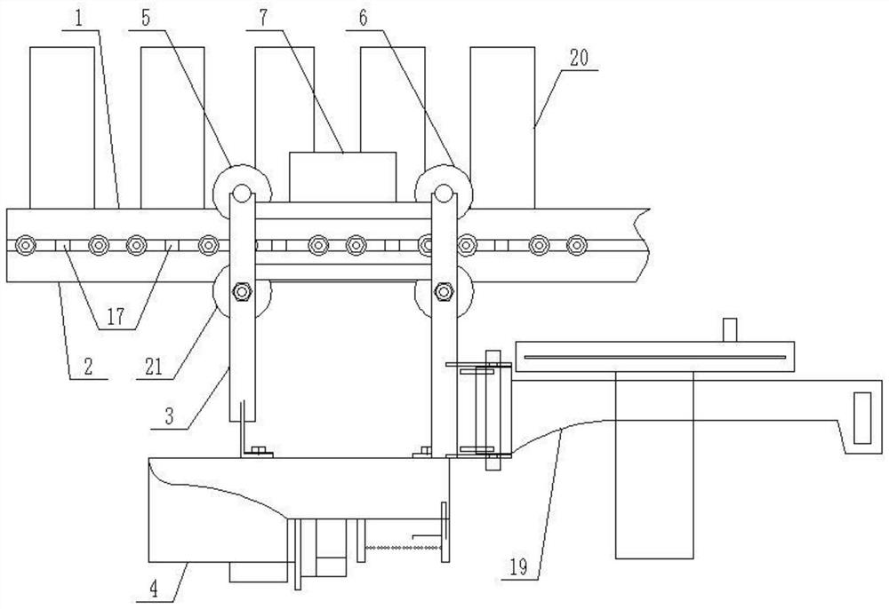
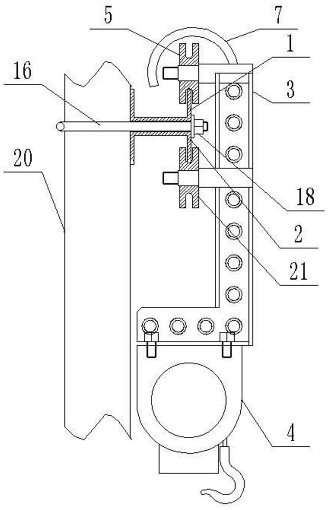
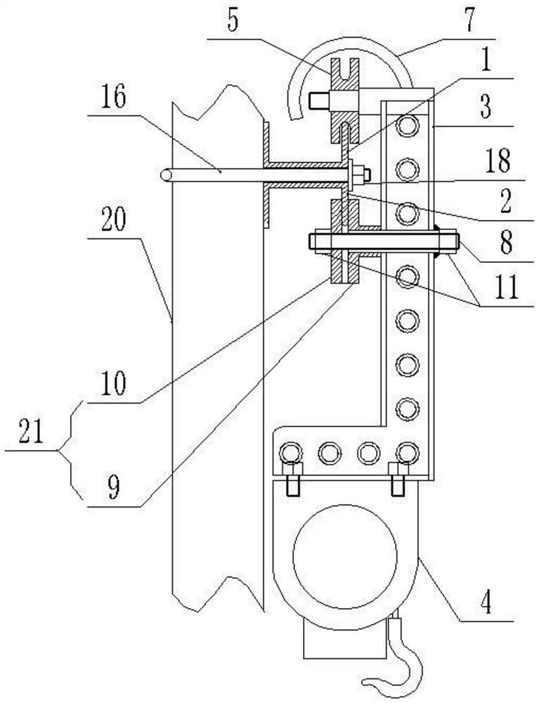
[0027] Such as figure 1 and figure 2 As shown, an embodiment of the present invention provides a furnace tube hoisting device, which includes: a guide rail and a moving part;

[0028] The guide rail is detachably connected t...


PUM


Abstract

The invention discloses a furnace tube hoisting device, relates to the technical field of hoisting, and mainly aims to improve the replacement and assembly efficiency of a cracking furnace tube. According to the main technical scheme, the furnace tube hoisting device comprises a guide rail and a moving part, wherein the guide rail is detachably connected to the shaft side of the upper furnace tubeof a cracking furnace, the guide rail comprises an upper edge plate and a lower edge plate, and the upper edge plate is fixedly connected to the lower edge plate; and the moving part comprises a railwheel, a rack and an auxiliary wheel, the rail wheel and the auxiliary wheel are rotationally connected to the same side of the rack, the rail wheel is connected to the upper edge plate in a rollingmode, the auxiliary wheel is connected to the lower edge plate in a rolling mode, and the lower end of the rack is connected to a hoisting mechanism.

Description

technical field [0001] The invention relates to the technical field of hoisting, in particular to a furnace tube hoisting device. Background technique [0002] In refining and chemical enterprises, the cracking furnace is used for a long time, and the furnace tube in the lower part of the cracking furnace will be deformed by heat, so the replacement and installation of the furnace tube is a very important task. Now, construction workers generally fix and bind the electric hoist to the upper furnace tube in the cracking furnace through short slings, then hoist the new furnace tube, and butt weld the new furnace tube and the upper furnace tube of the cracking furnace. [0003] But in the above-mentioned process, the short sling is easy to slip, and there is a certain danger in the hoisting process. The falling of the furnace tube can easily hurt the construction personnel at the bottom of the furnace, and the electric hoist is easy to swing, so that the electric hoist is diffi...

Claims


Application Information

Patent Timeline
IPC IPC(8): B66C17/00B66C9/08B66C7/08B66C11/00
CPCB66C7/08B66C9/08B66C11/00B66C17/00
Inventor 杜亮赖亚洲邵维新王启明方敏兰孙晨亮潘瑞赵玉军姜伟郭建成聂勇葛惠琴刘克车铭亭
Owner LIANHUA CONSTR GROUP XINJIANG
Why Eureka
Try Eureka