
Active control airfoil device and system of maglev train

A maglev train and active control technology, applied in the fields of noise, maglev train dynamics, and active control, can solve problems such as poor economic performance indicators, and achieve the effect of reducing energy consumption and improving braking capacity

Pending Publication Date: 2020-10-20
周先浚
View PDF0 Cites 3 Cited by
  • Summary
  • Abstract
  • Description
  • Claims
  • Application Information

AI Technical Summary

Problems solved by technology

This leads to the required electromagnetic force, especially the vertical electromagnetic force supporting the car body, which usually requires very thick wires or superconducting technology to deal with the thermal effect of the current. and noise, but the economic performance index is always worse than that of traditional wheel-rail vehicles

Method used


Image

  • Active control airfoil device and system of maglev train
  • Active control airfoil device and system of maglev train
  • Active control airfoil device and system of maglev train

Examples


Embodiment 1

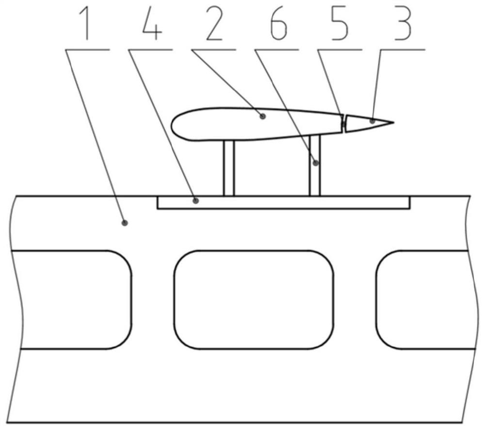
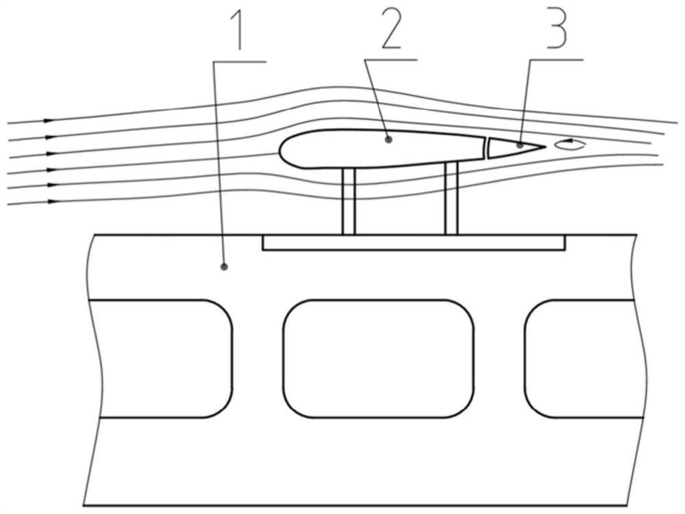
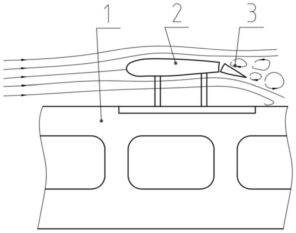
[0032] An active control airfoil device for a maglev train, such as Figure 1~3 As shown, it is arranged on the top of the maglev train 1, including the main airfoil 2 and the flap 3 connected to the rear edge of the main airfoil 2, the main airfoil 2 is located above the top of the maglev train 1, and can be relative to the maglev train 1 through the reversing assembly 4 The top rotates, and the angle between the flap 3 and the main airfoil 2 can be adjusted through the servo assembly 5 .

[0033] In this embodiment, the reversing assembly 5 in the present invention can use the electric energy of the maglev train 1, and is responsible for horizontally turning the direction of the main airfoil 2 during the stop and reversing of the maglev train 1, so that it faces the running direction of the maglev train 1. The steering assembly 5 maintains a locked state during the operation of the maglev train 1 . The main airfoil 2 is arranged on the reversing assembly 4 through the brack...

Embodiment 2

[0037] An active control airfoil system for a maglev train, comprising the active control airfoil device of Embodiment 1. Preferably the actively controlled airfoil system further comprises a controller. The controller is used to obtain train operation instructions and operation speed signals from the maglev train, convert the train operation instructions and operation speed signals to the servo components, and control the rotation angle of the flaps. At the same time, the controller also outputs to the maglev control system of the maglev train. Feedback, the maglev train system uses this to adjust the magnetic buoyancy. Further preferably, the controller is also used to convert the train operation command signal and transmit it to the reversing assembly, so that the maglev train controls the main airfoil to face the train running direction before the reversing operation. The controller can be independent of the maglev train control system (for example, using an independent s...


PUM


Abstract

The invention relates to the field of dynamics, noise and active control of maglev trains, in particular to an active control airfoil device and system of a maglev train. The active control airfoil device is arranged at the top of the maglev train and comprises a main airfoil and a flap connected to the rear edge of the main airfoil, the main airfoil is arranged above the top of the maglev train and can rotate relative to the top of the maglev train through a reversing assembly, and the angle between the flap and the main airfoil can be adjusted through a servo assembly. Lift compensation andresistance compensation are conducted on the maglev train based on the aerodynamic principle, specifically, a lift force is provided for an airfoil in the operation stage, and resistance is provided for airfoil turbulence in the braking stage. Compared with the prior art, the roof space of the maglev train is fully utilized, the energy consumption of a maglev system is reduced, and the braking capacity of the maglev train is improved.

Description

technical field [0001] The invention relates to the fields of dynamics, noise and active control of maglev trains, in particular to an active control airfoil device and system for maglev trains. Background technique [0002] Existing maglev trains rely entirely on electromagnetic force for suspension, traction and braking. This leads to the required electromagnetic force, especially the vertical electromagnetic force supporting the car body, which usually requires very thick wires or superconducting technology to deal with the thermal effect of the current, which also leads to the fact that the maglev train avoids the resistance of the wheel-rail operation and noise, but the economic performance index is always worse than that of traditional wheel-rail vehicles. Contents of the invention [0003] According to the principles of aerodynamics, a complete set of theoretical control aircraft has been formed in the field of aviation. However, maglev trains, especially high-spe...

Claims


Application Information

Patent Timeline
Patent Type & Authority Applications(China)
IPC IPC(8): B60T1/16B61D17/00B60L13/04
CPCB60L13/04B60T1/16B61D17/00
Inventor 周先浚周劲松
Owner 周先浚
Learn More