
Positioning device and automatic equipment

A technology of positioning device and positioning bracket, which is applied in mechanical equipment, transmission device, fluid pressure actuating device, etc., can solve the problems that motor transmission is difficult to solve, limit the use range of motor, and realize high cost, and achieve low cost and wide range of applications. , the effect of precise positioning

Pending Publication Date: 2020-10-16
彭心智
View PDF0 Cites 0 Cited by
  • Summary
  • Abstract
  • Description
  • Claims
  • Application Information

AI Technical Summary

Problems solved by technology

Initially, ordinary single-phase or three-phase motors and frequency converters are used to realize the realization. In order to achieve precise positioning control, the most widely used stepping system or servo system is currently on the market. This structure is accurate for position control, but the implementation cost is relatively high.
For some specific occasions, such as the occasions that require high levels of static electricity and inductive electricity, or require the use of explosion-proof motors, it is difficult for motor drives to solve the above problems, which limits the scope of use of the motor.

Method used


Image

  • Positioning device and automatic equipment
  • Positioning device and automatic equipment
  • Positioning device and automatic equipment

Examples


Embodiment Construction

[0036] The technical solutions of the present invention will be clearly and completely described below in conjunction with the accompanying drawings. Apparently, the described embodiments are some of the embodiments of the present invention, but not all of them. Based on the embodiments of the present invention, all other embodiments obtained by persons of ordinary skill in the art without making creative efforts belong to the protection scope of the present invention.

[0037] In the description of the present invention, it should be noted that the terms "center", "upper", "lower", "left", "right", "vertical", "horizontal", "inner", "outer" etc. The indicated orientation or positional relationship is based on the orientation or positional relationship shown in the drawings, and is only for the convenience of describing the present invention and simplifying the description, rather than indicating or implying that the referred device or element must have a specific orientation, ...


PUM


Abstract

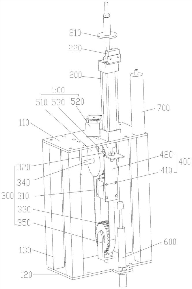
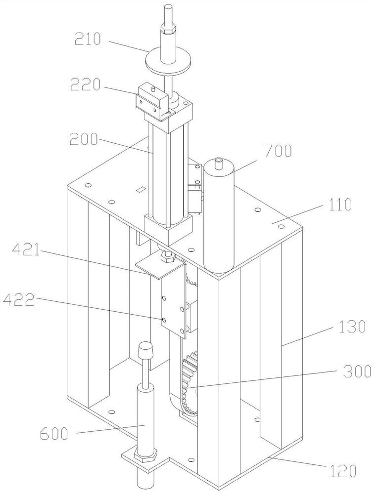
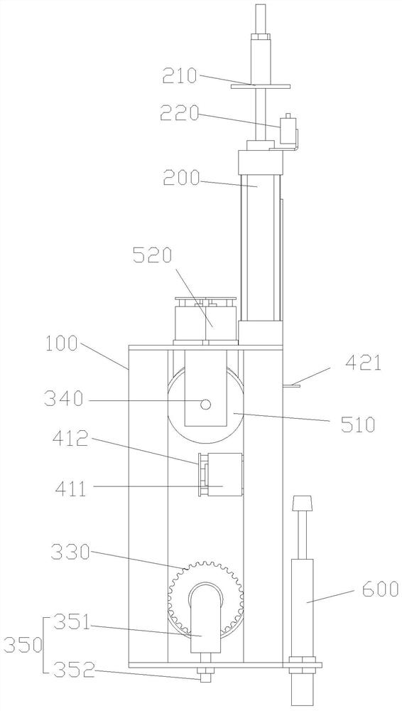
The invention provides a positioning device and automatic equipment, and belongs to the field of automatic equipment. The positioning device comprises a support frame, a first driving assembly, a conveying assembly and a clamping assembly; the supporting frame comprises a first supporting plate and a second supporting plate, the first driving assembly is arranged on the first supporting plate, thefirst driving assembly is provided with a telescopic rod moving in the direction perpendicular to the plane of the first supporting plate, and the telescopic rod penetrates through the first supporting plate; the clamping assembly comprises a clamping device and a positioning support, the positioning support is connected with the head end of the telescopic rod, and the clamping device is connected with one side of the positioning support; the conveying assembly comprises a belt wheel mechanism and a conveying belt, and the conveying belt is arranged between the clamping device and the positioning support in a penetrating mode; and the clamping device can clamp the conveying belt between the clamping device and the positioning bracket, so that the conveying belt and the telescopic rod movesynchronously, when the clamping device moves away from the conveying belt, the conveying belt is disengaged from the positioning support, and then accurate positioning of the conveying belt is achieved. the device has the advantages of being low in cost and wide in use occasion.

Description

technical field [0001] The invention relates to the field of automation equipment, in particular to a positioning device and automation equipment. Background technique [0002] With the development of the economy and the progress of society, energy conservation has become an inevitable and social consensus. All kinds of automation equipment are more and more developed in the direction of energy saving, convenient use, safety and high efficiency. As an important part of automation equipment, positioning control is no exception. [0003] Belt positioning controls are usually driven by electric motors. Initially, ordinary single-phase or three-phase motors and frequency converters are used to realize. In order to achieve precise positioning control, stepping systems or servo systems are most commonly used on the market. This structure is accurate for position control, but the implementation cost is relatively high. For some specific occasions, such as the occasions that requ...

Claims


Application Information

Patent Timeline
Patent Type & Authority Applications(China)
IPC IPC(8): F15B15/02F15B15/14F15B15/22F15B15/24F16H7/14F16H35/00
CPCF15B15/02F15B15/14F15B15/22F15B15/228F15B15/24F16H7/14F16H35/00
Inventor 彭心智彭显明
Owner 彭心智
Learn More