Arm body assembling machine of hydraulic buffer hinge

A technology of hydraulic buffering and assembling machine, applied in assembling machines, metal processing equipment, manufacturing tools, etc., can solve the problems of reducing work efficiency, inability to make wide openings, increasing the failure rate of products, etc., to improve the success rate, reduce Effects of manual assembly and pin insertion operations

Pending Publication Date: 2020-10-16
佛山市本吉智能科技有限公司
View PDF0 Cites 1 Cited by
  • Summary
  • Abstract
  • Description
  • Claims
  • Application Information

AI Technical Summary

Problems solved by technology

[0007] In the third installation process, sometimes the holes on the "pocket" and "plum blossom" and "lamination" are not aligned correctly, and the "U-shaped needle" cannot be inserted, and the installation action needs to be repeated once or twice. , multiple operations will also deform the "Douzai"
If the defective parts are mixed into the qualified semi-finished products, it will greatly increase the workload of the quality inspectors.
[0008] The manual assembly of the semi-finished products of the above hydraulic buffer hinges requires multiple processes. At the same time, in the first and second processes, the nail threading machine is easy to deform the arm body and cause the appearance of defective products.
However, when the pin is widened, it is more difficult to operate, and there are often situations where the wide opening cannot be made or the pin is bent.
In the third installation process, the holes of the pockets, plum blocks and laminations are often misaligned, and at the same time, the U-shaped needles cannot penetrate the pockets, plum blocks and stacks, so repeated installation is required. Repeated operations will deform the bag
Therefore, manual operation will reduce work efficiency and increase the failure rate of products

Method used


Image

  • Arm body assembling machine of hydraulic buffer hinge
  • Arm body assembling machine of hydraulic buffer hinge
  • Arm body assembling machine of hydraulic buffer hinge

Examples


Embodiment Construction

[0040] The present invention will be further described in detail below in conjunction with the accompanying drawings and specific embodiments. Terms such as "upper", "inner", "middle", "left", "right" and "one" quoted in this specification are only for the convenience of description, and are not used to limit the scope of the present invention. The scope of implementation and the change or adjustment of its relative relationship shall also be regarded as the scope of implementation of the present invention without substantive changes in technical content.

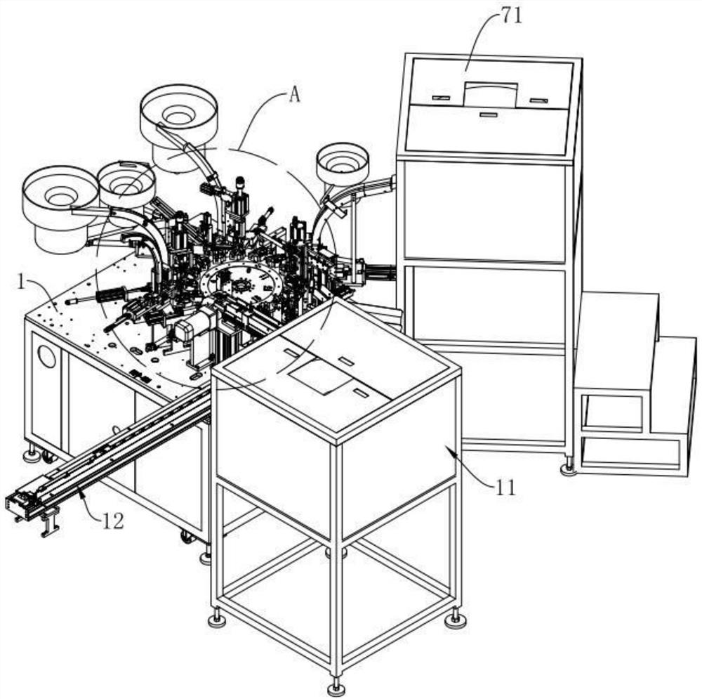
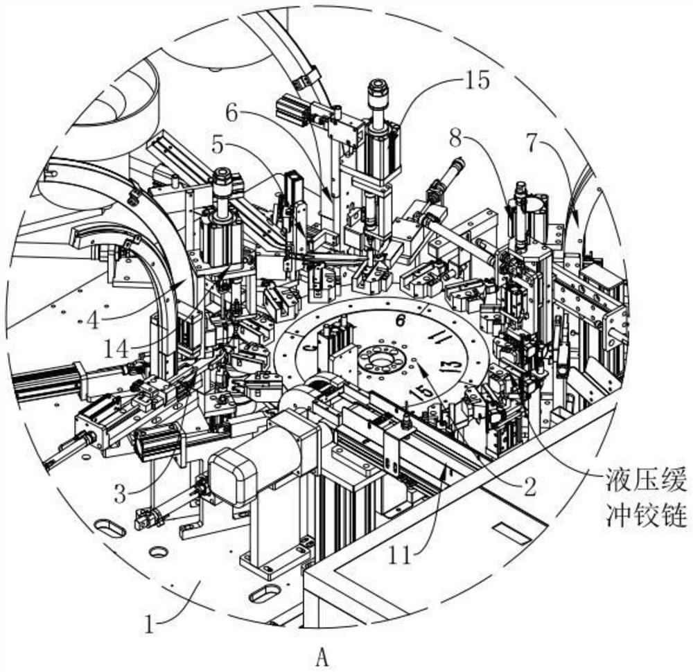
[0041] refer to figure 1 and figure 2 The shown arm body assembly machine of a hydraulic buffer hinge includes a frame 1 supported on the ground by rollers, the frame 1 is arranged in a cube, and the top surface of the frame 1 is connected with a motor through a screw lock (not shown in the figure). shown), the motor (not shown in the figure) is a deceleration servo motor, which can rotate intermittently according to de...


PUM


Abstract

The invention discloses an arm body assembling machine of a hydraulic buffer hinge. The arm body assembling machine is characterized by comprising a rack, the rack is provided with a rotating disc mechanism for installing a product, the rack is provided with a torsional spring mechanism and a plum blossom block mechanism for conveying a torsional spring and a plum blossom block into an arm body respectively, and the rack is provided with a main bolt mechanism for integrating the arm body, the plum blossom block and the torsional spring; the rack is provided with a colloidal particle mechanismand a lamination mechanism which are used for conveying colloidal particles and laminations into the arm body respectively, and the rack is provided with an auxiliary bolt mechanism for integrating the arm body, the laminations and the colloidal particles; and the rack is provided with a pocket mechanism for conveying pockets to be matched with the plum blossom blocks and the laminations, and therack is provided with a U-shaped needle mechanism for integrating the pockets, the plum blossom blocks and the laminations. By the adoption of the arrangement, the torsional spring mechanism, the plumblossom block mechanism, the lamination mechanism and the pocket mechanism are sequentially used for installing the torsional spring, the plum blossom block, the laminations and the pockets on the arm body through the rotating effect of the rotating disc mechanism, and the advantages of intelligently assembling the arm body, improving the percent of pass and improving the production efficiency are achieved.

Description

technical field [0001] The invention relates to the technical field of hinge assembly equipment, in particular to an arm body assembly machine for a hydraulic buffer hinge. Background technique [0002] Hydraulic hinge is a kind of hinge, also known as damping hinge, which refers to providing a kind of noise-absorbing buffer hinge that uses high-density oil body to flow directionally in a closed container to achieve ideal buffering effect. The existing disclosed hydraulic buffer hinge includes an arm body, a torx block, a torsion spring, laminations, rubber particles and a pocket. One end of the arm body and an end of the torx block are plugged together by pins, and the torsion spring is connected to the arm body and torx block. One end of the torsion spring is connected to the arm body, and the other end of the torsion spring is connected to the plum blossom block. The lamination is located in the plum blossom block. One end of the lamination is inserted and matched with th...

Claims


Application Information

Patent Timeline
Patent Type & Authority Applications(China)
IPC IPC(8): B23P21/00
CPCB23P21/006
Inventor 梁大伟吴辉张堂梁霍敏耀邱新福陈游国曾伟宋玉玮
Owner 佛山市本吉智能科技有限公司
Why Eureka
Try Eureka