
Air fryer with multiple cavities

An air fryer, multi-cavity technology, applied in kitchen utensils, home utensils, roasters/barbecue grids, etc., can solve problems such as rising costs, complex internal structures, and long time consumption, and achieve manufacturing cost control. , the effect of shortening working time and shortening cooking time

Pending Publication Date: 2020-10-16
宁波曼华电器有限公司
View PDF0 Cites 2 Cited by
  • Summary
  • Abstract
  • Description
  • Claims
  • Application Information

AI Technical Summary

Problems solved by technology

However, the existing air fryer has a relatively uniform structure, resulting in the same heating method, which cannot meet the higher-level needs of consumers
Existing air fryers have at least the following defects, for example: 1. There is only a single heating chamber or frying basket, and only one kind of food can be processed at a time, and the cooking time of various foods is different. Taking meat as an example, it generally requires It takes tens of minutes, so sometimes when it is necessary to process a variety of foods or a large amount of food, it cannot be cooked at one time, and it takes a long time; 2. Due to the inability to heat multiple foods or a large amount of food at the same time, air frying The pot needs to work for a long time, so it can neither achieve efficient cooking, energy saving and environmental protection, but also accelerate the aging of various components, which greatly reduces the service life; 3. In the traditional thinking, multiple sets of heating components are required to achieve multiple chambers. In this way, the overall volume of the air fryer will become very large and heavy, the internal structure will become very complicated, and the operation will be very inconvenient. At the same time, the biggest problem is that the cost will increase greatly, and many favored by most consumers

Method used


Image

  • Air fryer with multiple cavities
  • Air fryer with multiple cavities
  • Air fryer with multiple cavities

Examples


Embodiment Construction

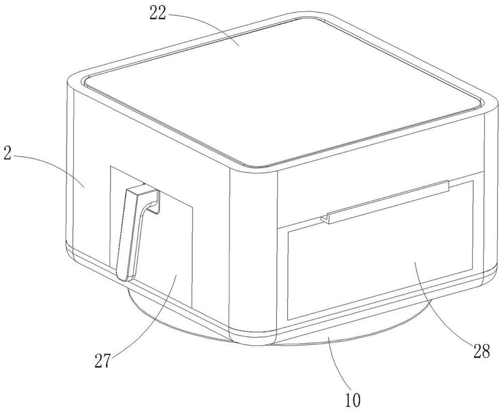
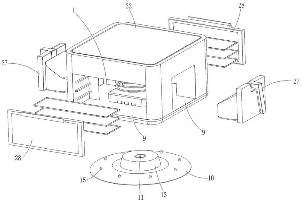
[0036] The present invention will be described in further detail below in conjunction with the accompanying drawings and specific embodiments.

[0037] refer to Figure 1 to Figure 10 , a multi-cavity air fryer, including a fryer body 2 with an inner cavity 1, a frying container assembly, a heating assembly arranged in the fryer body 2, and a control circuit assembly ( not shown in the figure), the inner chamber 1 is divided into an installation chamber 3 and several heating chambers 4, the installation chamber 3 communicates with each heating chamber 4, and each heating chamber 4 is arranged around the installation chamber 3 on the outer peripheral side;

[0038] The heating assembly includes a motor 5, a hot air vane 6 arranged in the installation cavity 3 and driven by the motor 5, and a heating pipe assembly 7 vertically arranged in the installation cavity 3, and the hot air vane 6 includes The blade base 7 arranged horizontally, and the guide part 8 formed by extending ...


PUM


Abstract

The utility model discloses an air fryer with multiple cavities. The air fryer comprises a fryer body with an inner cavity, a frying container assembly, a heating assembly arranged in the fryer body and a control circuit assembly in control connection with the heating assembly, the inner cavity is divided into an installation cavity and a plurality of heating cavities, the installation cavity is communicated with the heating cavities, and the heating cavities are arranged on the peripheral sides of the installation cavity in a surrounding mode; the heating assembly comprises a motor, a hot airblade arranged in the mounting cavity and driven by the motor, and a heating pipe assembly arranged in the mounting cavity in the vertical direction, and the hot air blade comprises a horizontally-arranged blade base part and a flow guide part formed by extending the blade base part downwards; each heating cavity is provided with an inlet and an outlet, the frying container assembly is provided with a plurality of independent container units, and the container units correspond to the heating cavities in a one-to-one mode. According to the air fryer, the multiple heating cavities can be provided through the single fryer body, so that the requirement for synchronously heating and cooking various foods can be met, and the total cooking time is shortened.

Description

technical field [0001] The invention relates to the technical field of air fryers, in particular to an air fryer with multiple cavities. Background technique [0002] The air fryer uses high-speed air circulation technology, and combines the rapid circulation of hot air and the unique combination of internal spiral lines so that the cooking effect can achieve the effect and taste of fried food. In layman's terms, when heating, high-temperature hot air will be generated in the pot to form a crispy surface on the surface of the food, lock the moisture inside the food, and achieve the fragrant and crispy taste of ordinary fried food. [0003] As people pay more attention to dietary health, air fryers for oil-free cooking are becoming more and more popular among consumers, and sales are increasing year by year. However, the structure of the existing air fryer is relatively uniform, resulting in the same heating method, which cannot meet the higher-level needs of consumers. Exi...

Claims


Application Information

Patent Timeline
Patent Type & Authority Applications(China)
IPC IPC(8): A47J37/06
CPCA47J37/0641A47J37/0664
Inventor 胡杰
Owner 宁波曼华电器有限公司
Learn More