Seawater treatment device for protecting marine organisms
A technology for marine organisms and seawater, which is applied in the field of seawater treatment devices for marine organism protection and can solve problems such as garbage dispersion
- Summary
- Abstract
- Description
- Claims
- Application Information
AI Technical Summary
Problems solved by technology
Method used
Image
Examples
Embodiment 1
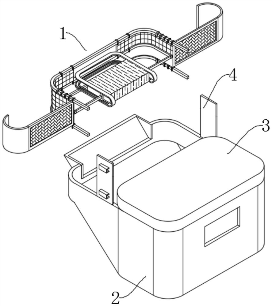
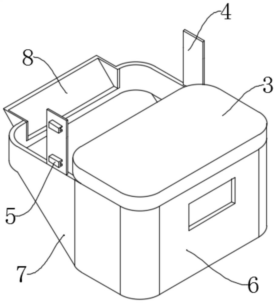
[0032] see Figure 1-5 , a seawater treatment device for marine life protection, comprising an intercepting mechanism 1 and a collection box 1, the intercepting mechanism 1 is fixedly connected to the upper side of the collection box 1, the collection box 2 includes a lowering box 7 and a garbage disposal box 6, and the lowering box 7 Fixedly connected to one side of the garbage disposal box 6, the upper end of the garbage disposal box 6 is fixedly connected with a transmission box 3, the upper end of the collection box 2 is fixedly connected with a fixed plate 4 on both sides, and the intercepting mechanism 1 is fixedly connected with the lower material box 7 through the fixed plate 4; A drive mechanism 14 is arranged in the center of the inner side of the interception mechanism 1, and the drive mechanism 14 includes a mounting frame 21, which is fixedly connected to the upper side wall of the transmission box 3, and a circulation box 19 is fixedly connected to the inside of t...
Embodiment 2
[0035] see Figure 2-4, based on Example 1, the difference is that:
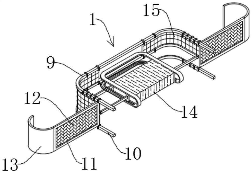
[0036] The intercepting mechanism 1 includes a guide rail A9 and a guide rail B10, the guide rail A9 is arranged above the guide rail B10, the ends of the guide rail A9 and the guide rail B10 are connected through the inside of the sliding sleeve block 5, and one side of the sliding sleeve block 5 is fixedly connected to the side wall of the fixed plate 4; the guide rail A9 An intercepting net B15 is arranged between the guide rail B10, and several sliding rings 16 are fixedly connected to the upper and lower sides of the intercepting net B15, and the sliding rings 16 are slidably connected to the guide rail A9 and the guide rail B10;
[0037] An interception frame 11 is fixedly connected between the sliding rings 16 at the end of the interception net B15, the interior of the interception frame 11 is fixedly connected with an interception net A12, and the outer side of the interception frame 11 is fixedly co...
Embodiment 3
[0041] see Figure 5-6 , based on Embodiment 1 and 2, the difference is that:
[0042] The interior of the circulation box 19 is provided with a biaxial motor 23, which is fixedly connected to the interior of the circulation box 19 through a fixed block; the output shafts at both ends of the biaxial motor 23 are respectively fixedly connected with a connecting shaft 24, and the ends of the connecting shaft 24 are fixedly connected with a cone Conical wheel A26, conical wheel A26 upper meshing is connected with conical wheel B27, and conical wheel B27 fixed Liani forehead is at one end of screw rod 25, and the other end of screw rod 25 is movably connected to the lower end of fixed plate 28, and the upper end of fixed plate 28 is fixedly connected to Inside the circulation box 19; the back side of the slider 20 is fixedly connected with a movable piece, and the movable piece is threaded on the surface of the screw 25; the end of the screw 25 and the connecting shaft 24 are mova...
PUM
 Abstract
Description
Claims
Application Information
 - Generate Ideas
- Intellectual Property
- Life Sciences
- Materials
- Tech Scout
- Unparalleled Data Quality
- Higher Quality Content
- 60% Fewer Hallucinations
Browse by: Latest US Patents, China's latest patents, Technical Efficacy Thesaurus, Application Domain, Technology Topic, Popular Technical Reports.
© 2025 PatSnap. All rights reserved.Legal|Privacy policy|Modern Slavery Act Transparency Statement|Sitemap|About US| Contact US: help@patsnap.com


