
Fluid pipeline bypass structure

A fluid pipeline and fluid tube technology, applied in the field of temperature control equipment auxiliary devices, can solve the problems of response lag, fatigue loss, and inability to sense fluid pressure in real time, and achieve accurate reflection, adjustment of opening, and improvement of timeliness of response Effect

Pending Publication Date: 2020-10-09
无锡迈泰科技有限公司
View PDF0 Cites 0 Cited by
  • Summary
  • Abstract
  • Description
  • Claims
  • Application Information

AI Technical Summary

Problems solved by technology

There are two problems in this way: 1. Response lag, due to the existence of spring force, the change of fluid pressure cannot be sensed in real time; 2. Spring 12 will inevitably lead to fatigue loss during long-term work, and the change of spring force must be adjusted by adjustment pole 16

Method used


Image

  • Fluid pipeline bypass structure
  • Fluid pipeline bypass structure
  • Fluid pipeline bypass structure

Examples


Embodiment Construction

[0023] The utility model will be described in detail below in conjunction with the accompanying drawings. The description in this part is only exemplary and explanatory, and should not have any limiting effect on the protection scope of the present invention.

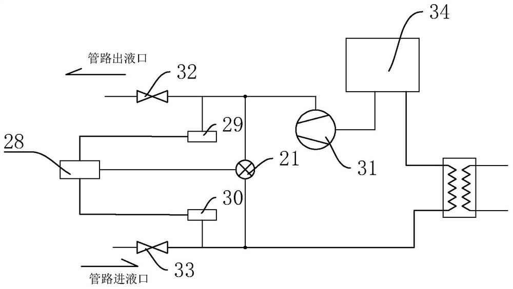
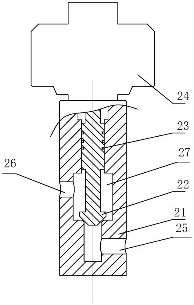
[0024] The present invention provides a fluid pipeline bypass structure, including a bypass structure main body 21 and a fluid pipeline structure;

[0025] The main body 21 of the bypass structure is connected in the fluid pipeline structure;

[0026] The fluid pipeline structure includes a second ball valve 33 and a first ball valve 32 arranged at the pipeline liquid inlet and pipeline liquid outlet; it is arranged between the first ball valve 32 and the bypass structure main body 21 The first pressure sensor 29; the second pressure sensor 30 arranged between the second ball valve 33 and the bypass structure main body 21; and the first pressure sensor 29, the second pressure sensor 30, the bypass structure The main bo...


PUM


Abstract

The invention provides a fluid pipeline bypass structure. The fluid pipeline bypass structure is used for pressure relief and flow division of a fluid pipeline of temperature control equipment so as to achieve the purpose of protecting a water pump; the fluid pipeline bypass structure comprises a bypass structure main body 21 and a fluid pipeline structure; the bypass structure main body 21 is connected in the fluid pipeline structure; the fluid pipeline structure comprises a second ball valve 33, a first ball valve 32, a first pressure sensor 29, a second pressure sensor 30 and a controller 28; the second ball valve 33 and the first ball valve 32 are arranged at a pipeline liquid inlet and a pipeline liquid outlet; the first pressure sensor 29 is arranged between the first ball valve 32 and the bypass structure main body 21; the second pressure sensor 30 is arranged between the second ball valve 33 and the bypass structure main body 21; and the controller 28 is separately connected with the first pressure sensor 29, the second pressure sensor 30 and the bypass structure main body 21. The fluid pipeline bypass structure has the beneficial effects that passive pressure change sensing is changed into active pressure change sensing so that the response timeliness can be improved; and stepping motor control is adopted so that the pressure change can be reflected more accurately, and the opening degree can be adjusted in time.

Description

technical field [0001] The invention relates to the field of temperature control equipment auxiliary devices, in particular to a fluid pipeline bypass structure. Background technique [0002] With the development of semiconductors and the wide application of temperature control equipment, the bypass structure of the fluid pipeline is generally added to the fluid pipeline of the temperature control equipment. The main purpose is to relieve pressure and divert flow and protect the water pump. [0003] In the bypass structure of the existing equipment, the mechanical structure is mostly used to achieve the bypass purpose (such as the attached image 3 ), this structure mainly adjusts the position of the guide device 14 through the adjustment rod 16 to realize the adjustment of the stroke of the spring 12, thereby adjusting the minimum opening pressure of the guide rod 13. In the actual operation process, because the pressure of the fluid is not constant, resulting in The positi...

Claims


Application Information

Patent Timeline
IPC IPC(8): F17D1/14F17D3/01F16K1/32F16K31/04F16K37/00
CPCF16K1/32F16K31/046F16K37/0091F17D1/14F17D3/01
Inventor 戴忠林
Owner 无锡迈泰科技有限公司
Learn More