
Photoluminescent marker system

A technology of photoluminescence and photoluminescent materials, which is applied in the field of photoluminescent marker systems, can solve problems such as printing difficulties, and achieve the effect of reducing cost and complexity

Pending Publication Date: 2020-10-09
SAF T GLO
View PDF9 Cites 0 Cited by
  • Summary
  • Abstract
  • Description
  • Claims
  • Application Information

AI Technical Summary

Problems solved by technology

It has been found that printing on paints used to enhance the durability of coverings is particularly difficult

Method used


Image

  • Photoluminescent marker system
  • Photoluminescent marker system
  • Photoluminescent marker system

Examples


Embodiment Construction

[0085] figure 1 It is a schematic diagram of an aircraft including an emergency evacuation lighting system. A typical arrangement of the interior of the cabin 1 of a passenger aircraft is shown. The seats 2 are arranged in rows 3 on opposite sides of the central aisle 4. In this embodiment, five seats are shown in each row 3, and the five seats are arranged in two groups on one side of the central aisle 4 and three in groups on the opposite side of the central aisle 4. However, this is not necessary and it should be understood that the number and arrangement of seats 2 in each row 3 can be changed, while providing a central aisle 4 that separates groups of seats 2 in each row 3 to facilitate Enter in the direction of the length of the cabin 1. It should also be understood that a single central aisle can be provided or a double aisle can be provided.

[0086] The exit 5 is provided at the front and rear of the cabin 1 so that passengers can get on and off the aircraft in normal...


PUM

PropertyMeasurementUnit
radiusaaaaaaaaaa

Abstract

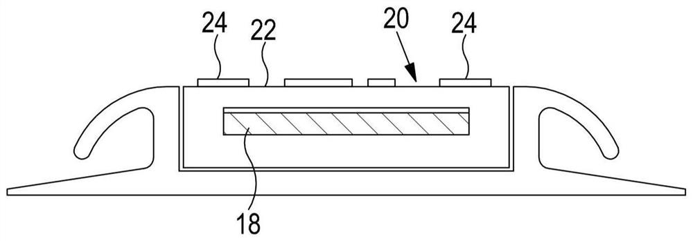
The invention relates to a photoluminescent marker system. The invention discloses a method for manufacturing the photoluminescent marker of an aerial vehicle, wherein the photoluminescent marker including a substrate at least is supplied. The method comprises the steps of 1) providing an ink or coating adapted to be cured with ultra violet (UV) radiation; ii) printing one or more markings directly onto the substrate of the photoluminescent marker with the ink or coating; iii) the marking comprises at least one of a pattern, wording, images, blocks, or indicia; iv) wherein the substrate is onein a photoluminescent material and a housing; and v) curing the ink or the coating by means of UV radiation. The invention further provides a photoluminescent marker of the aerial vehicle, wherein the photoluminescent marker marker of the aerial vehicle comprises a substrate and a layer comprising the ink or the coating mark which is directly printed on the substrate, wherein the ink or the coating is a composition which is cured through UV radiation.

Description

Technical field [0001] The present invention relates to an improved photoluminescent marker and an improved method of manufacturing the photoluminescent marker. Background technique [0002] In the case of a commercial aircraft emergency, it can provide guidance to identify the route to the exit and exit markers. In addition, markers can be used to identify various parts of the aircraft cabin or equipment. The route from the passenger seat to the emergency exit is usually indicated by emergency route markers provided on the floor of the aircraft cabin. Usually, the emergency path marker is located in the aisle area of ​​the aircraft cabin. The emergency path marker may be provided in the form of a strip extending along one or both sides of the aisle. [0003] Emergency exits can be marked by exit signs. In order to facilitate the safe evacuation of the aircraft cabin in an emergency, the emergency exit marker must be visible in the dark. [0004] In addition, in some cases, it i...

Claims


Application Information

Patent Timeline
Patent Type & Authority Applications(China)
IPC IPC(8): C09D5/22C09D11/03C09D11/50C09D11/101B64D47/02B41M5/00
CPCC09D5/22C09D11/03C09D11/50C09D11/101B64D47/02B41M5/0023B41M5/0047B41M5/0064B41J3/407B41M7/0081G09F13/20B41J11/00214B60Q3/46B64D11/00B64D2011/0038B64D2045/007C09D133/08
Inventor S·奥凯尔A·J·哈利特
Owner SAF T GLO
Learn More